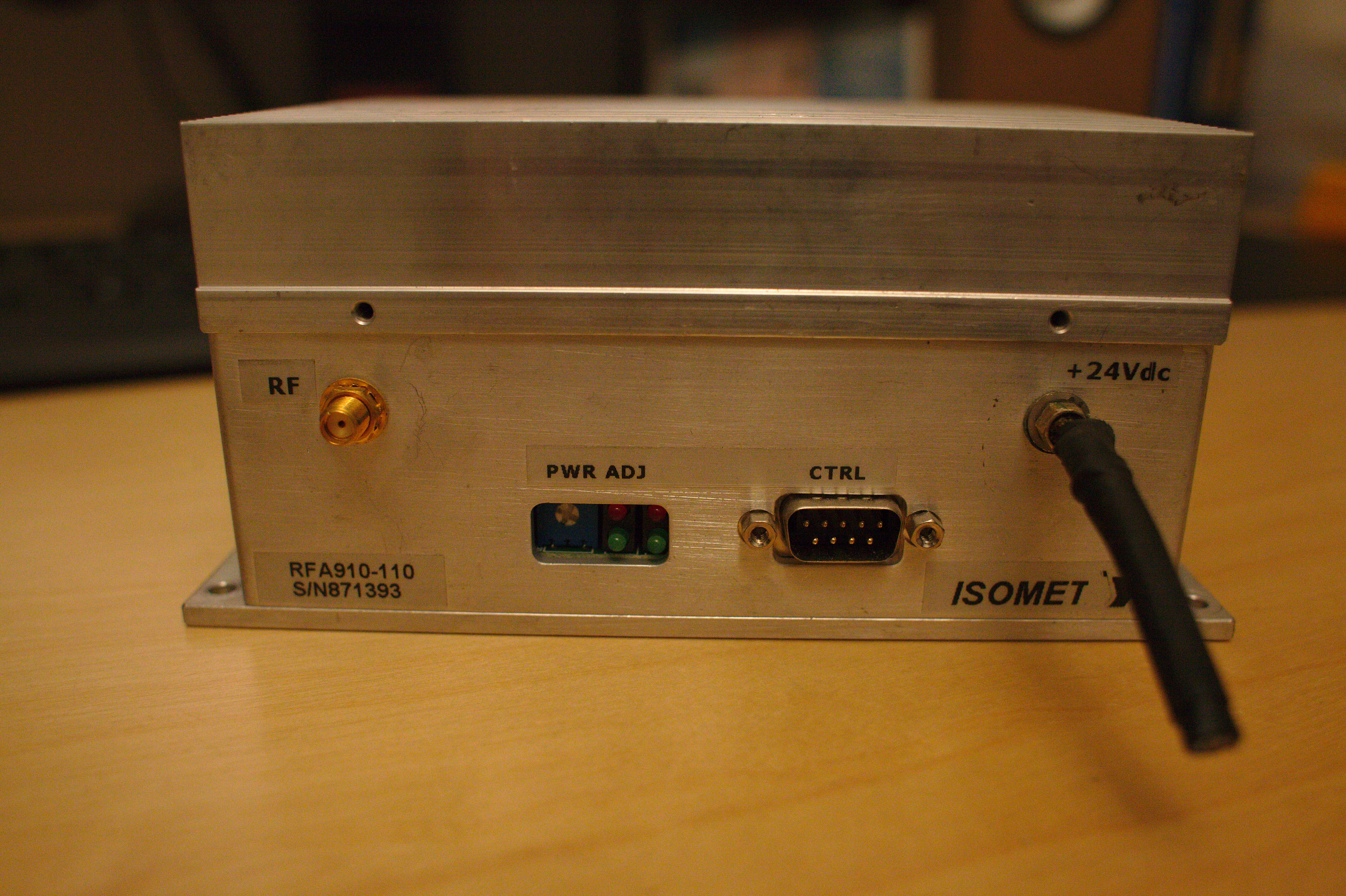
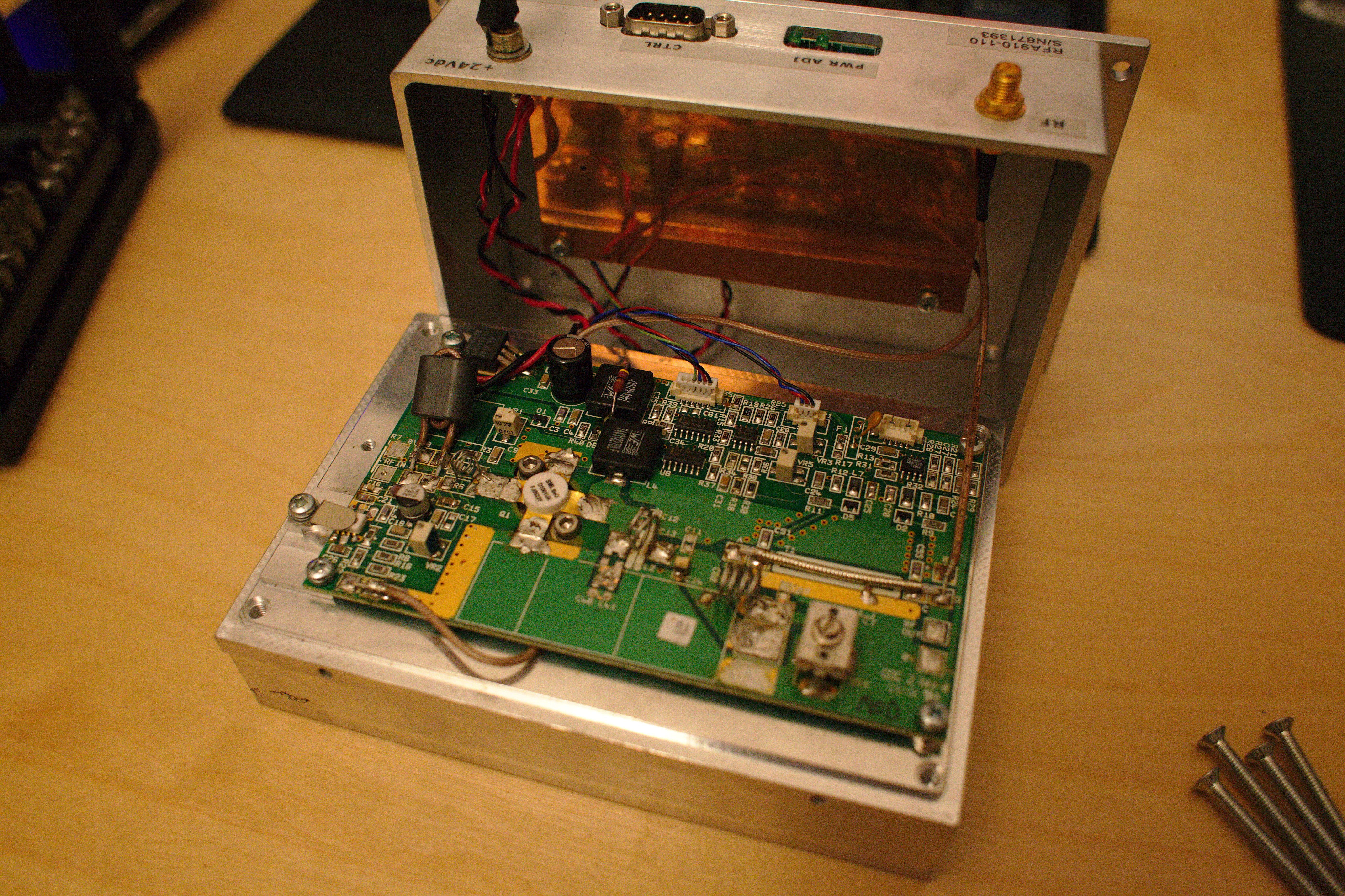
Some time ago I fished a "ISOMET RFA910-110 Acousto-Optic Modulator Driver" from a junkbin at my universities informatics lab. The responsible persons there did not even knew what this thing was, neither were it was used. It presumeable was residing there for a long time. Because the lab was renovated, they tossed out a lot of old stuff.
I took the thing mainly because of the nice aluminium casing. There is an application note for this thing and it explains a little bit for what it is used.
Clearly, someone had already a go with it. There are desoldered parts and some are probably replaced. There are also a lot of bodges where I'm not sure if they are applied already in the factory or when already in use. The difference in soldering quality favours the first therory...
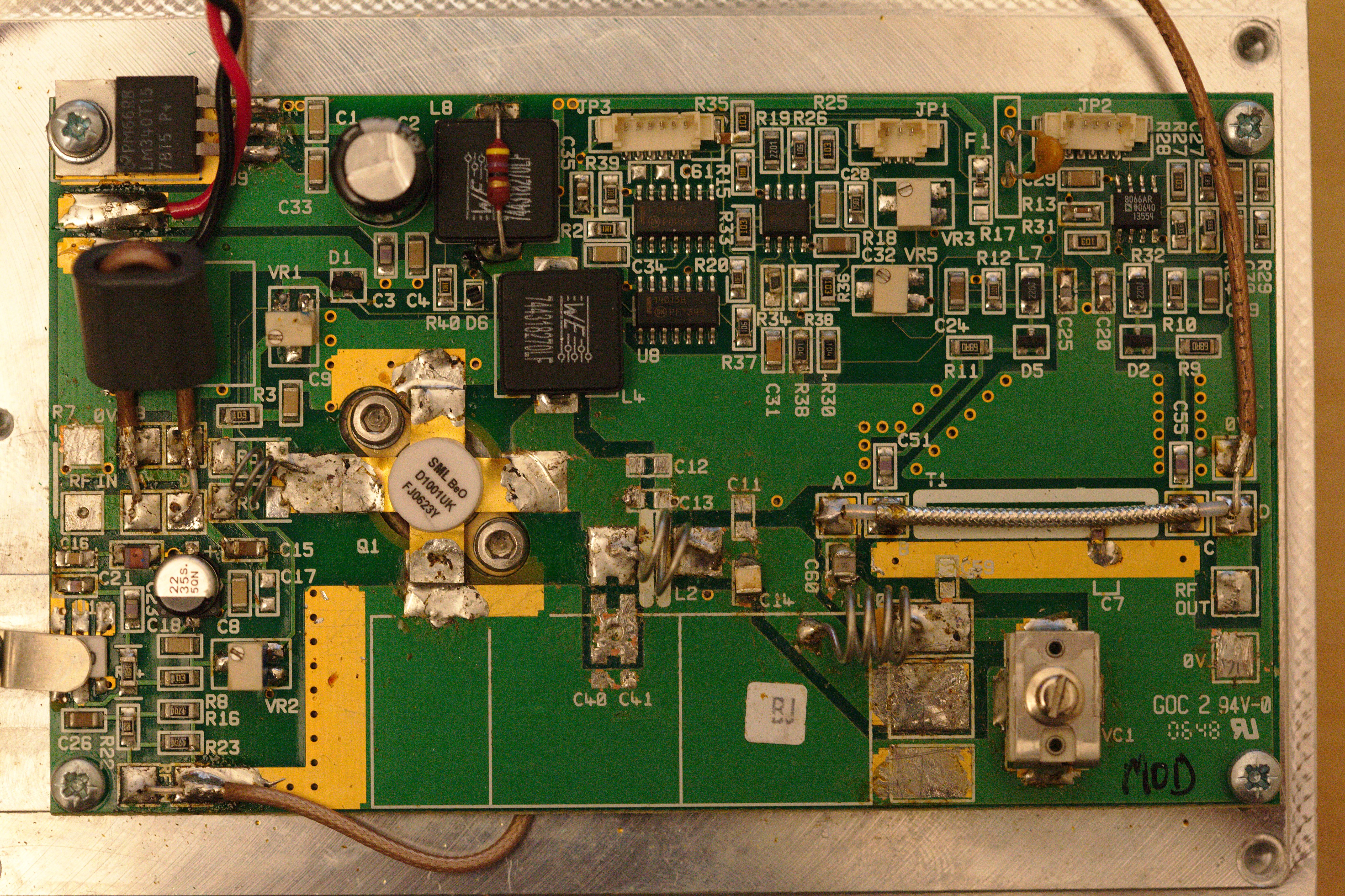
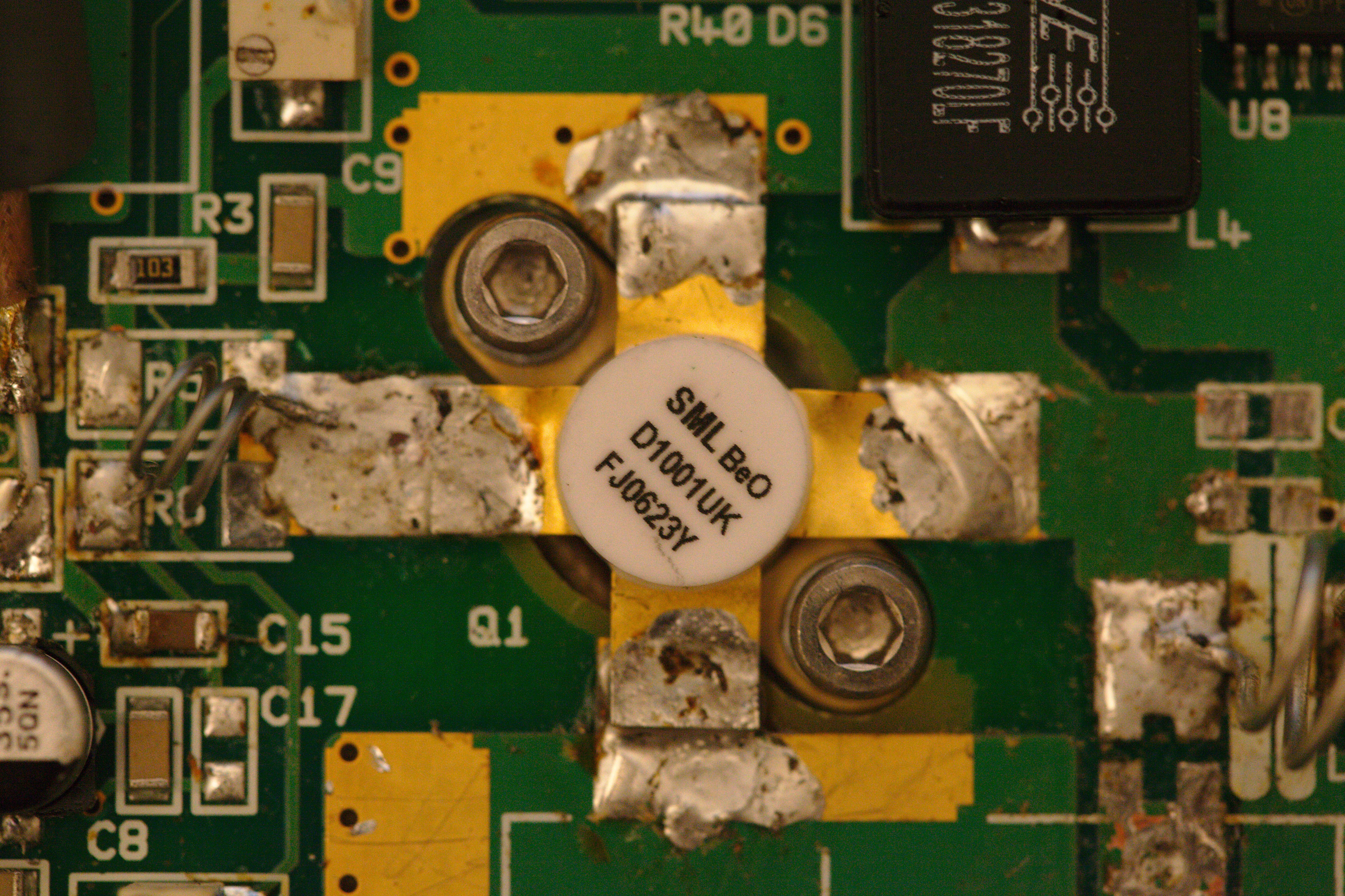
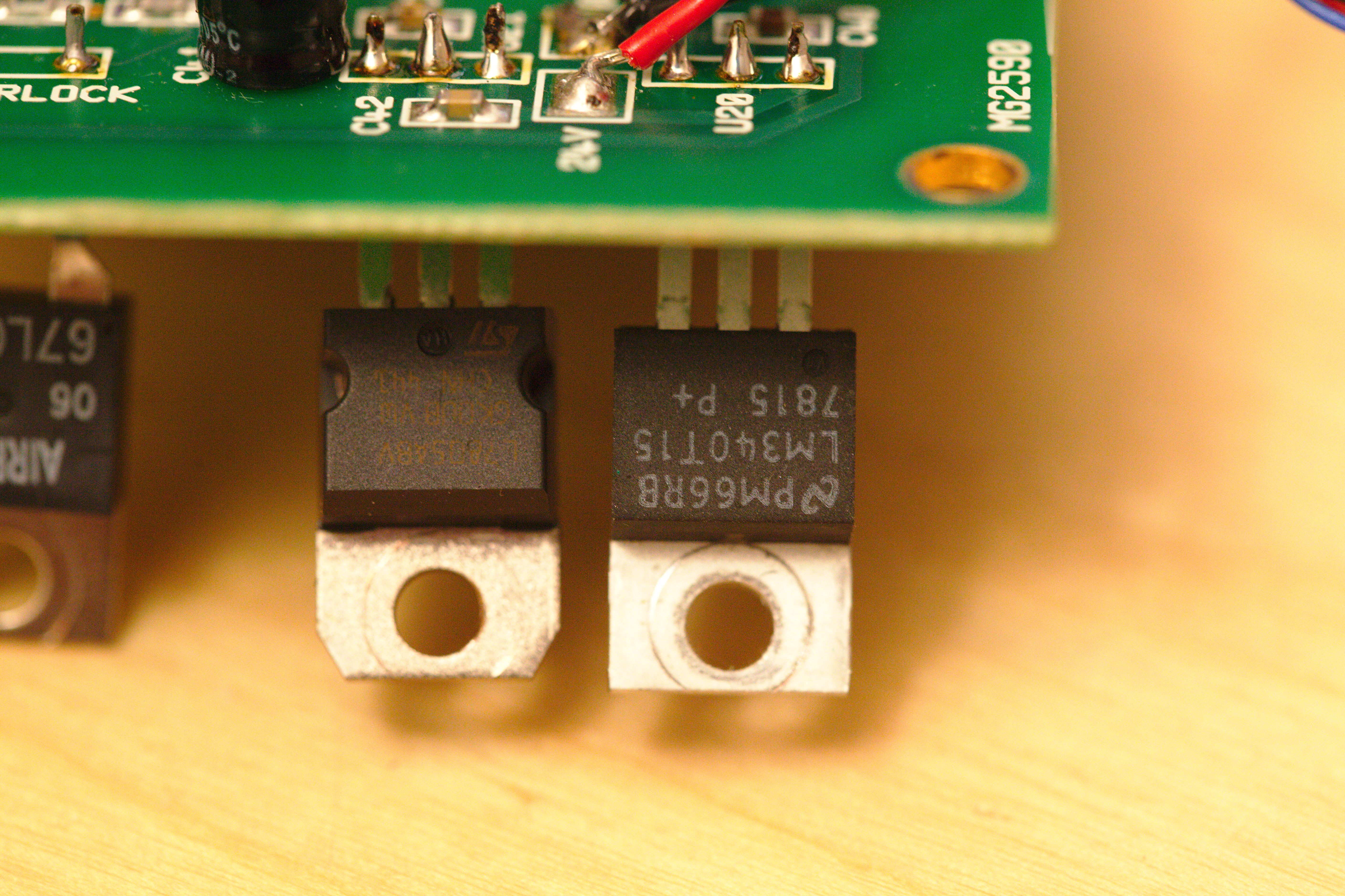
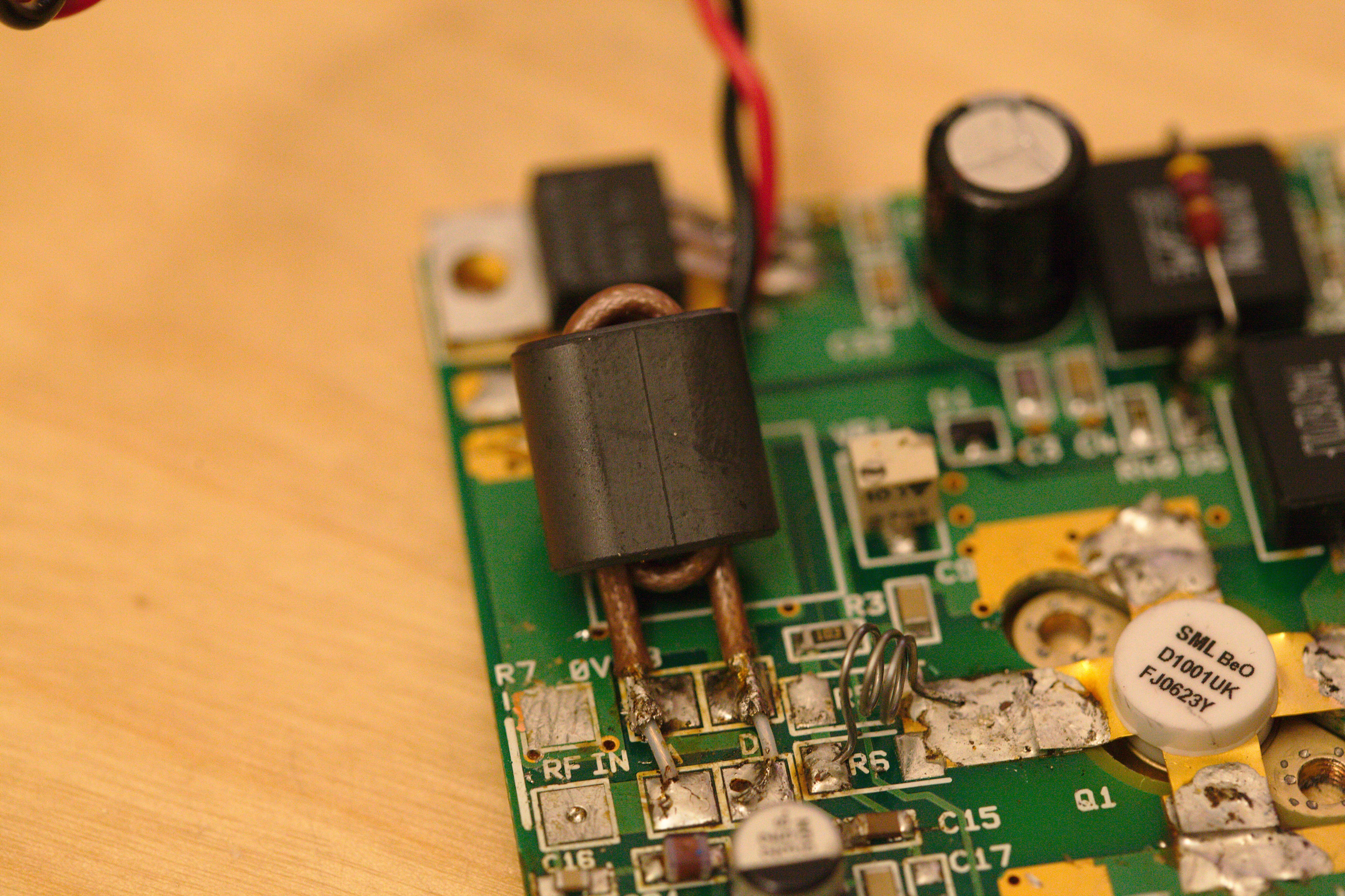
It seems like the amplifing transistor (a SEME LAB D1001UK DMOS RF FET) was replaced, as well as all the hand bend inductors in the RF path. Also the LM340 on the amplifier board seems to be replaced. Maybe some power surge killed all the parts? It certainly looks like the whole amplifier board was reworked. The I/O board looks very fresh in comparison.
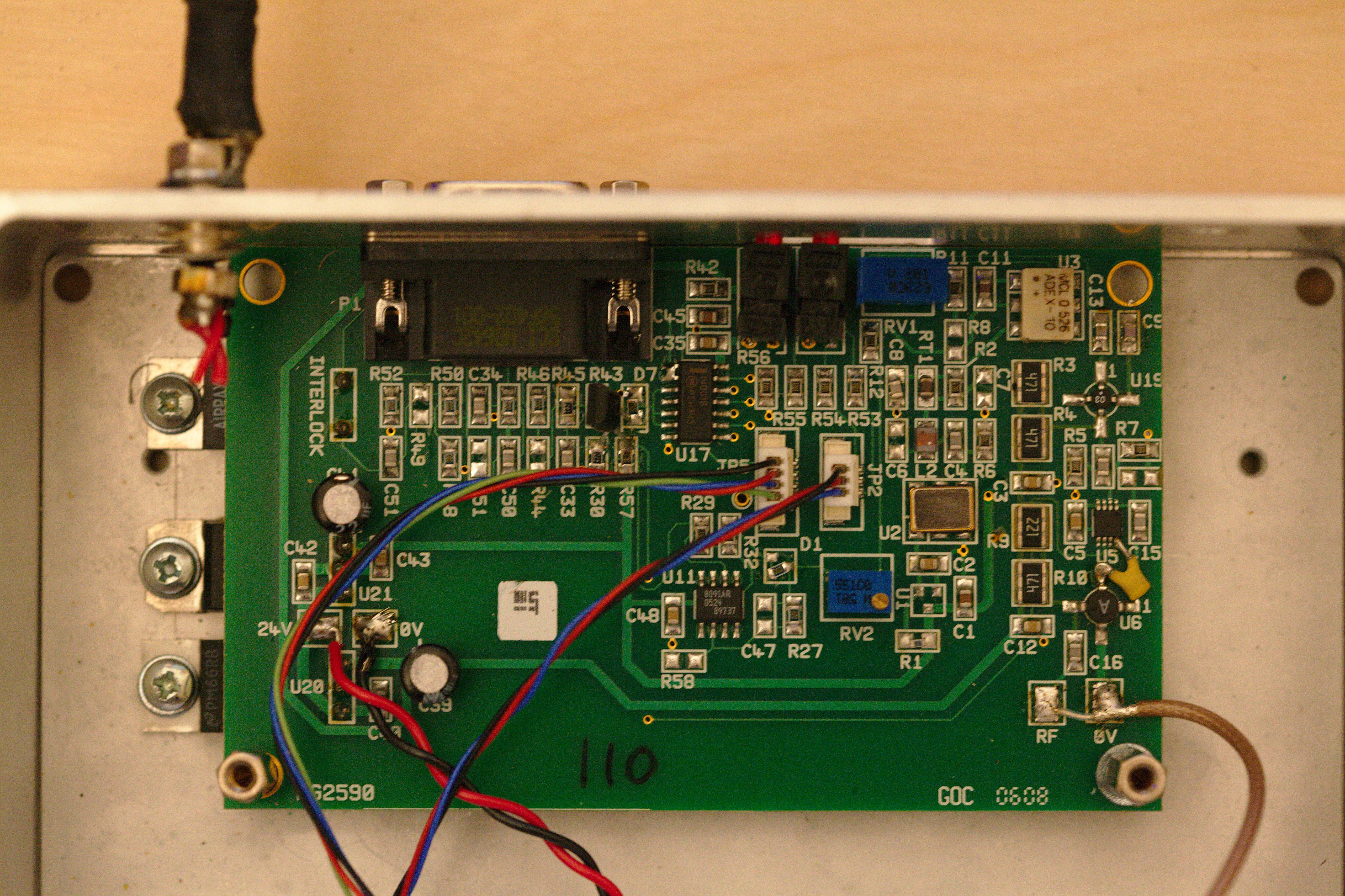
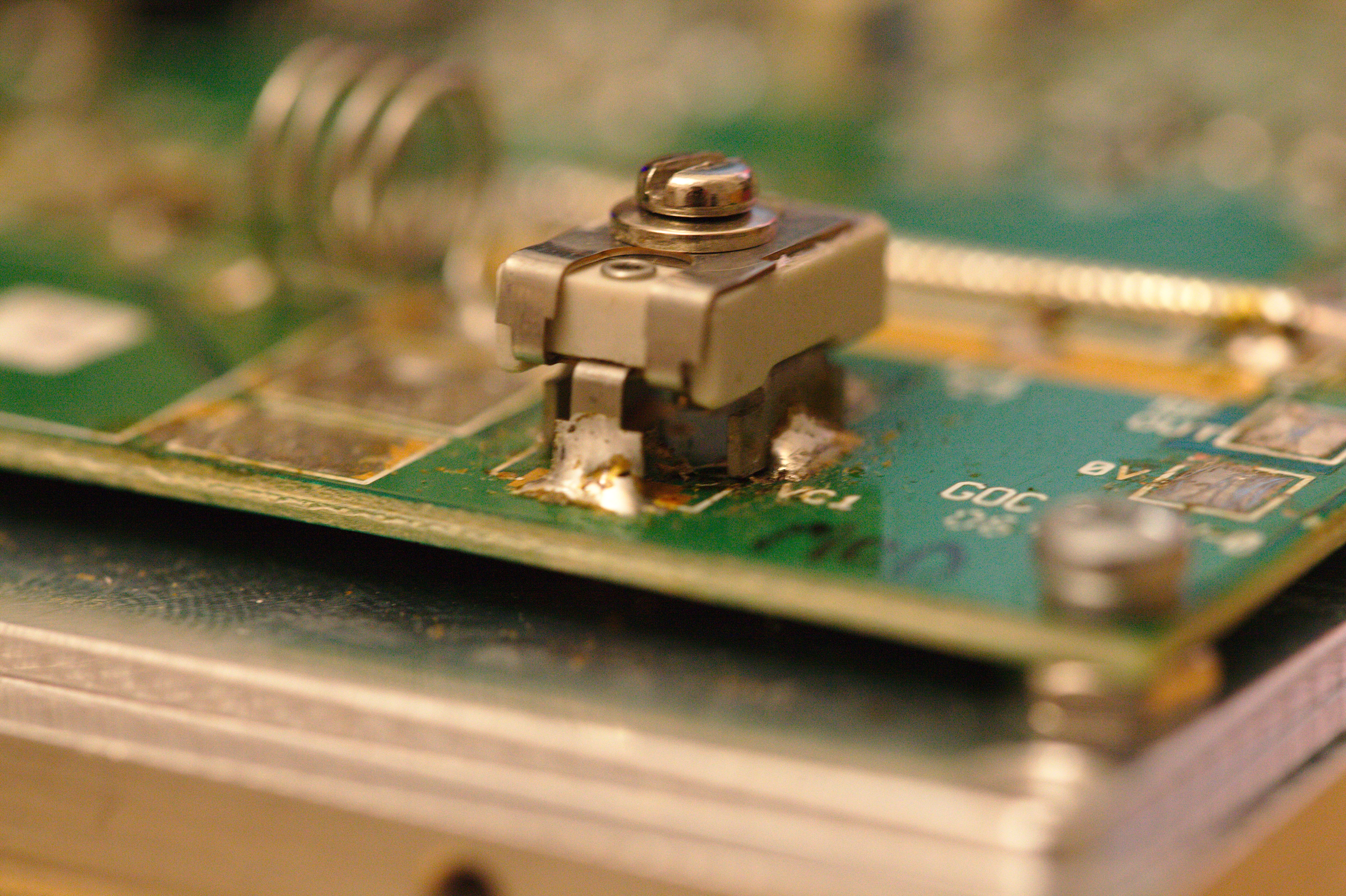
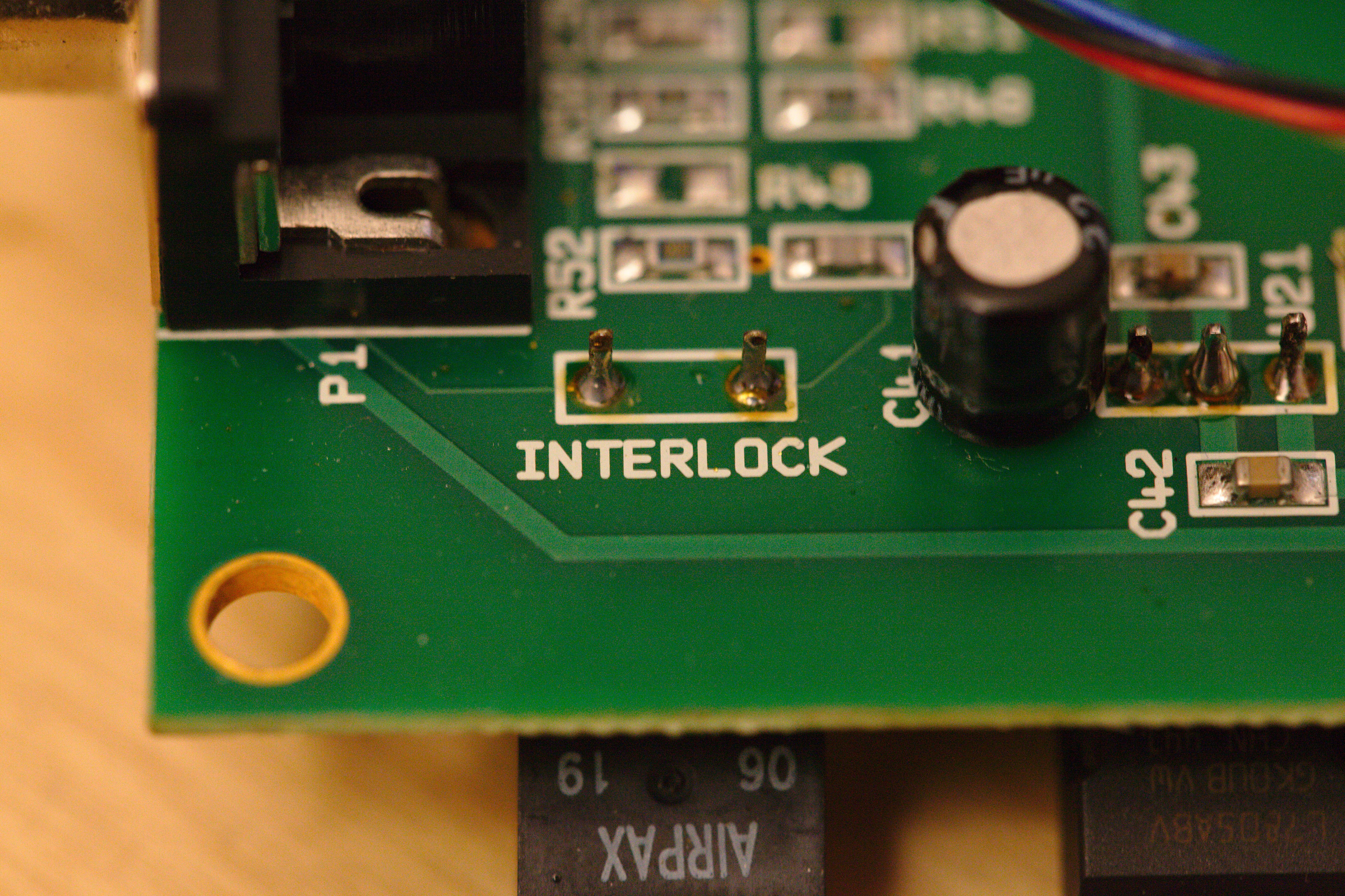
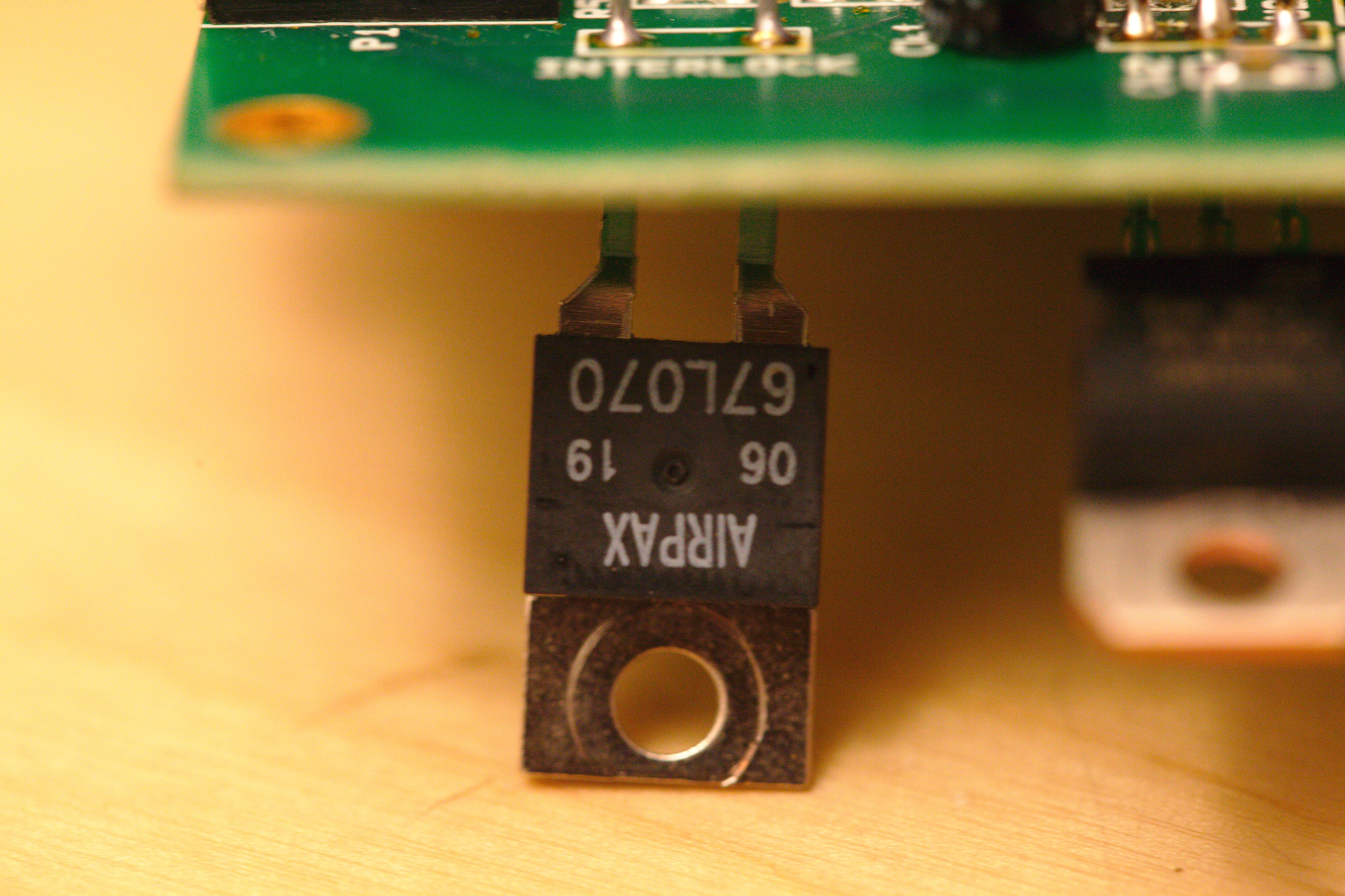
One interessting thing is the INTERLOCK switch on the I/O board. This is connected to a bimetal thermostat for 70°C. Because it is connected to the bottom of the casing, the actual chip temperature at the amplifier will be probably much higher if the switch opens.
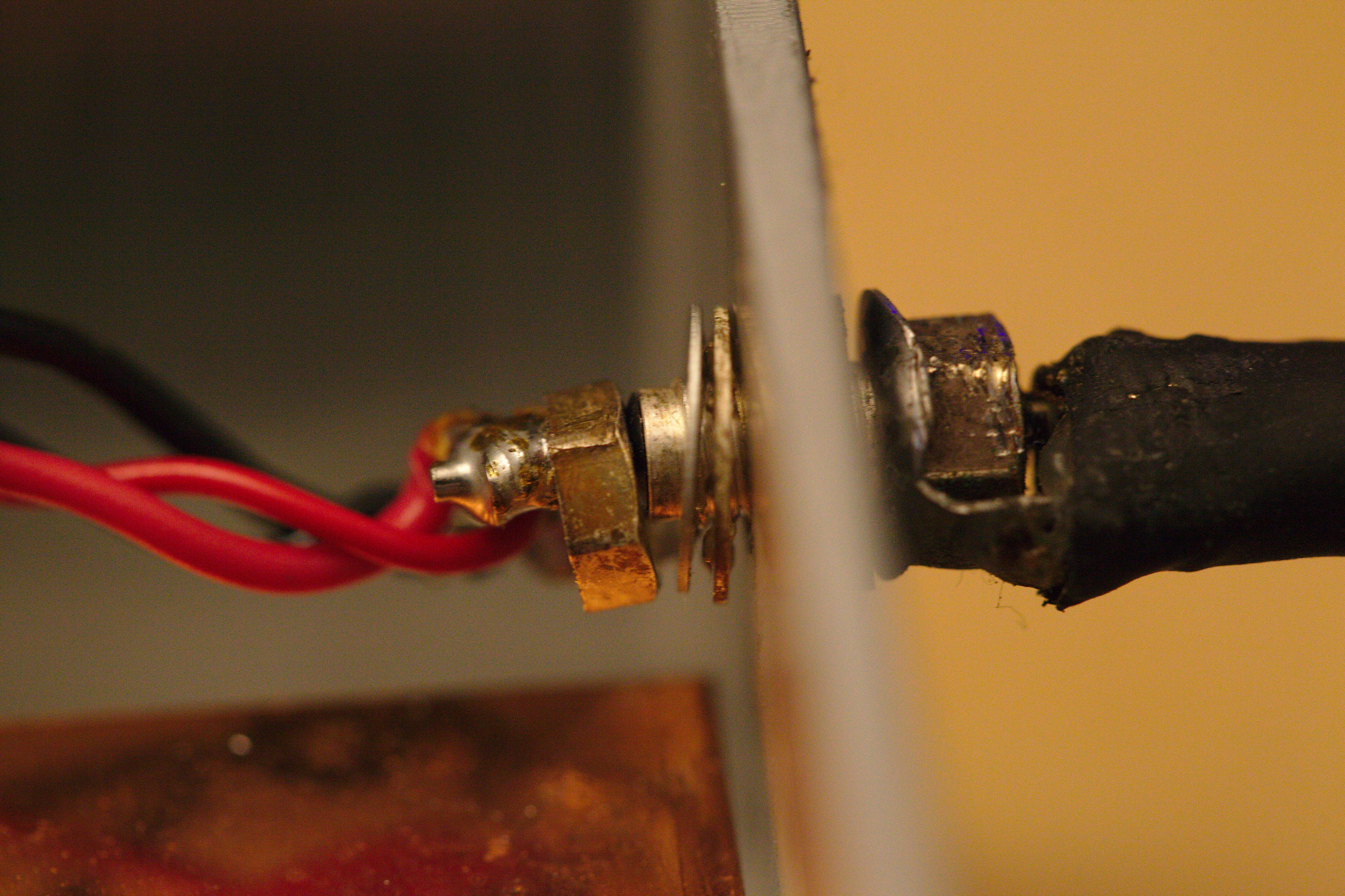
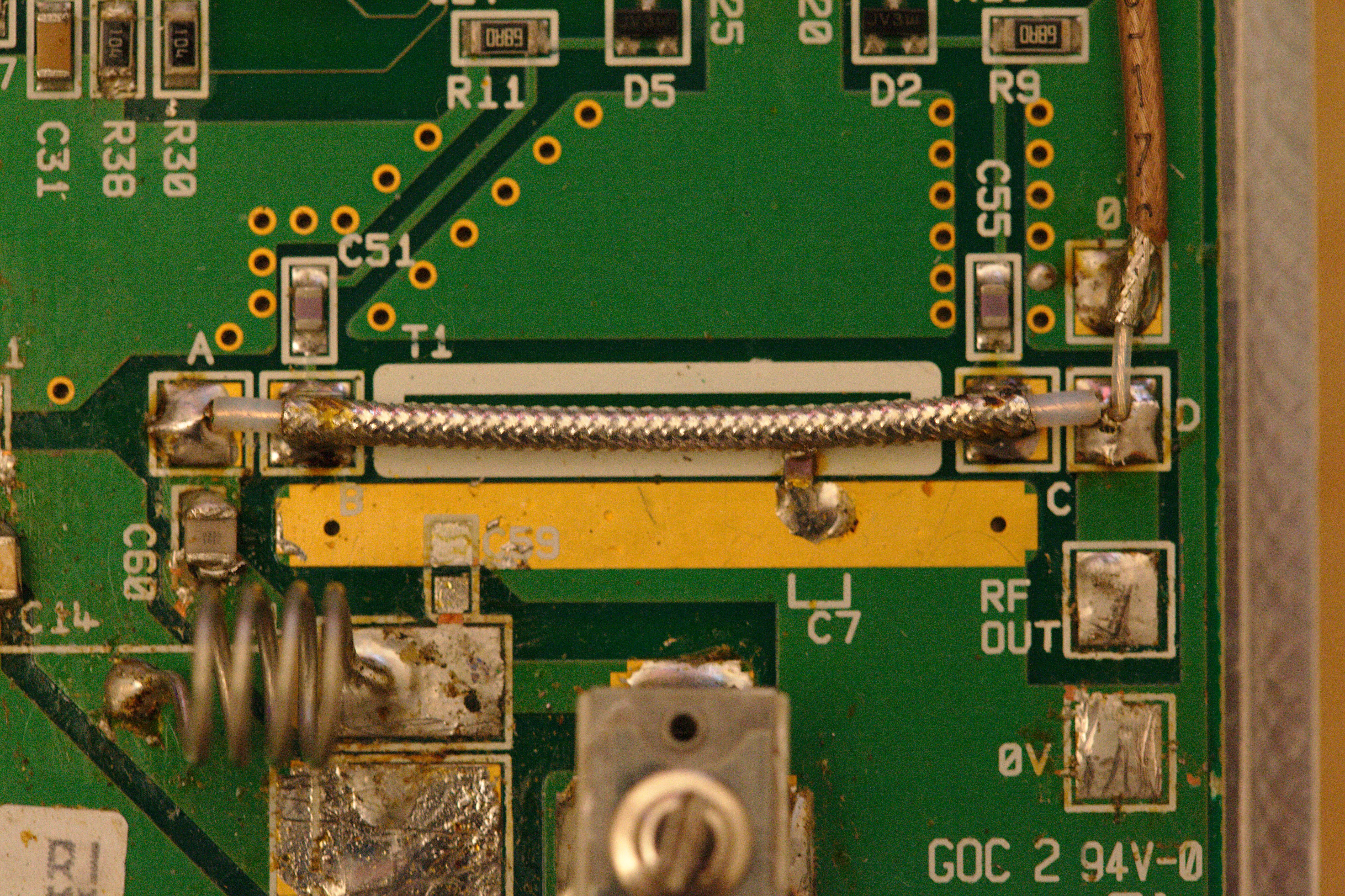
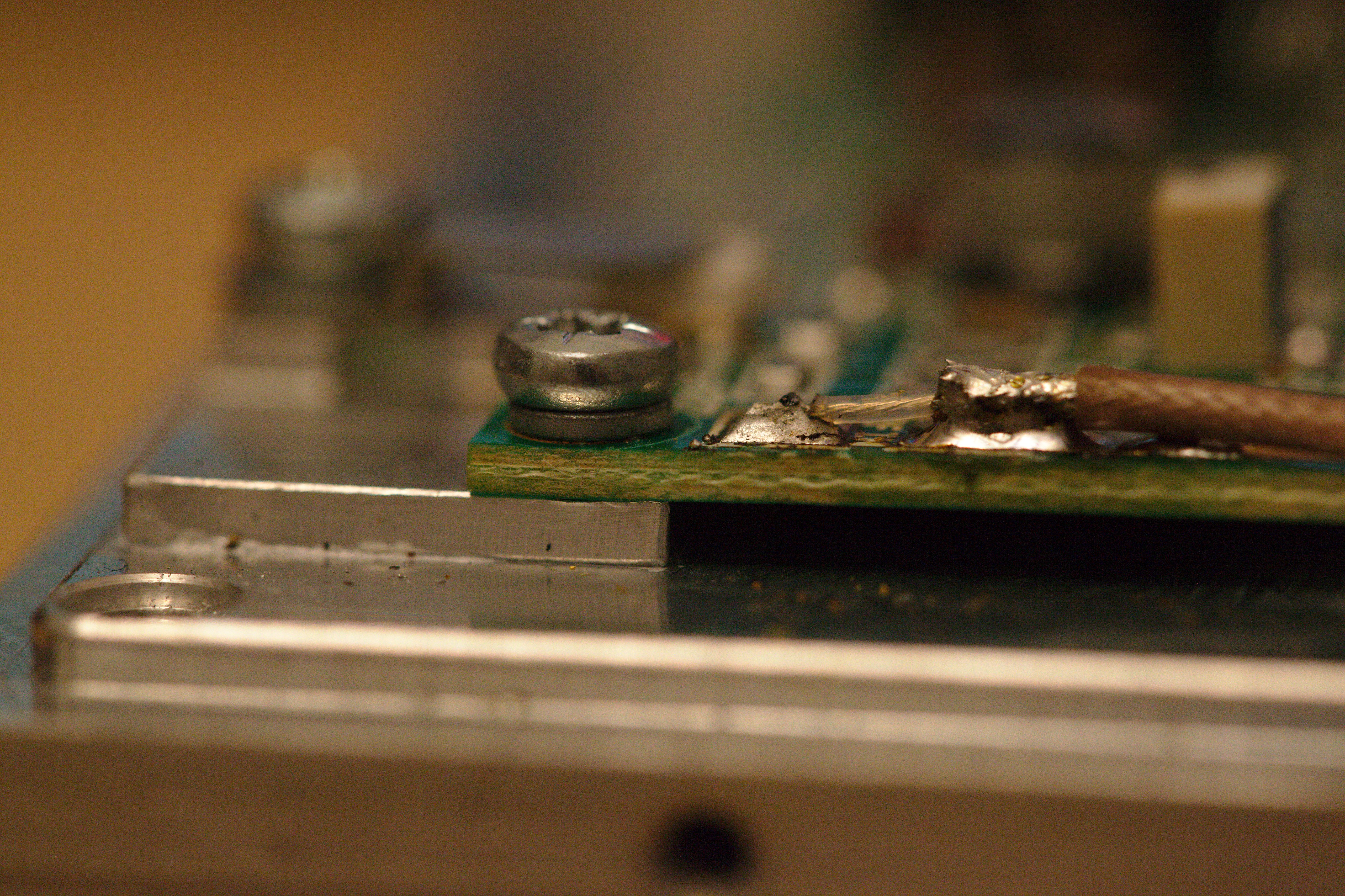
What I really found interessting, was that they used connectors for the data cables but power and RF was soldered. for the RF connection it sounds logical, as a connector is quite expensive and there is a connector at the outside of the case. But for power connection? Also the soldering there looks quite messy, thus I think this is not like it was in the original.
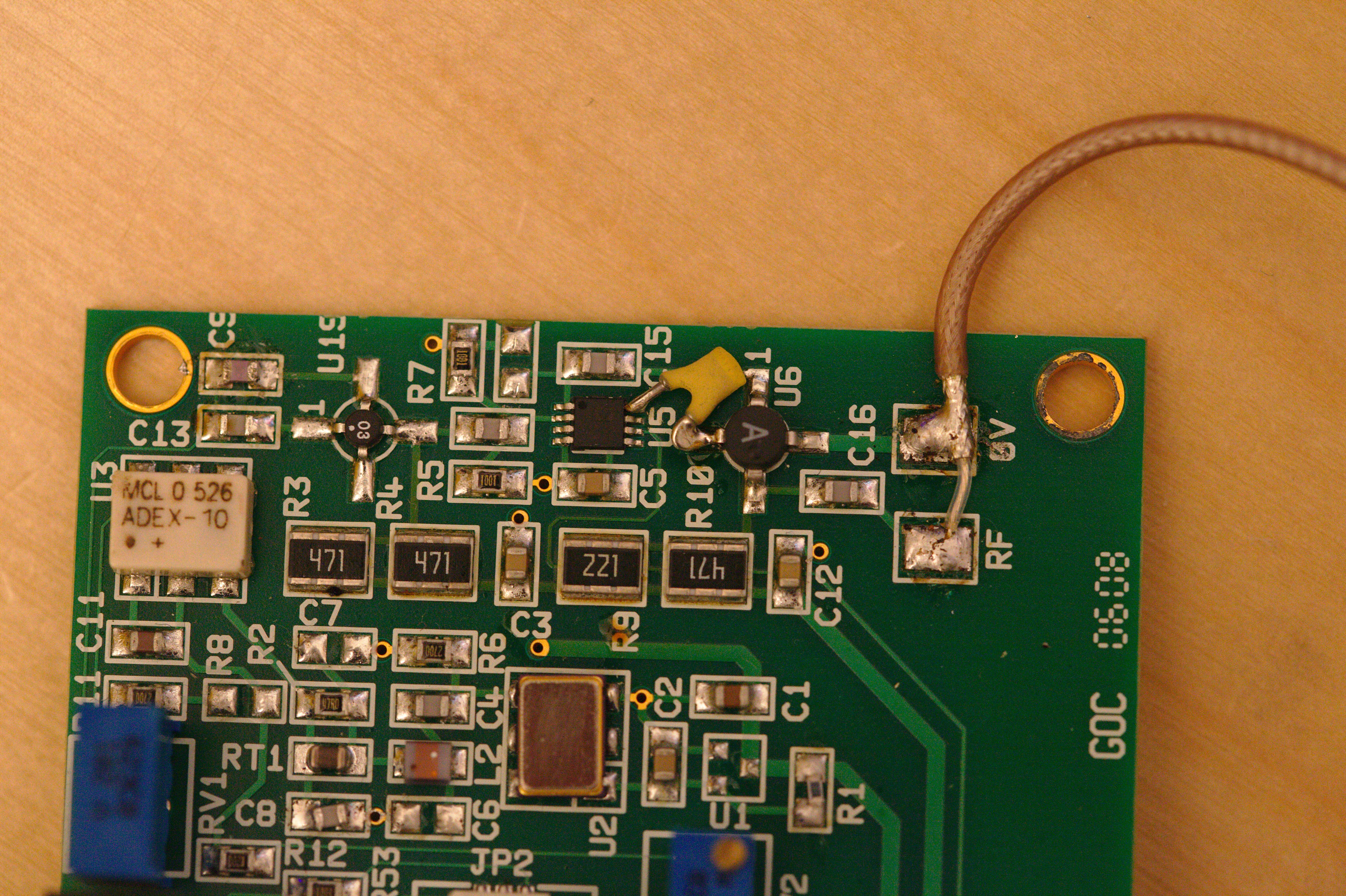
The I/O Board contains a quartz and a mixer IC ADEX-10. From this section goes a RF cable to the amplifier board.
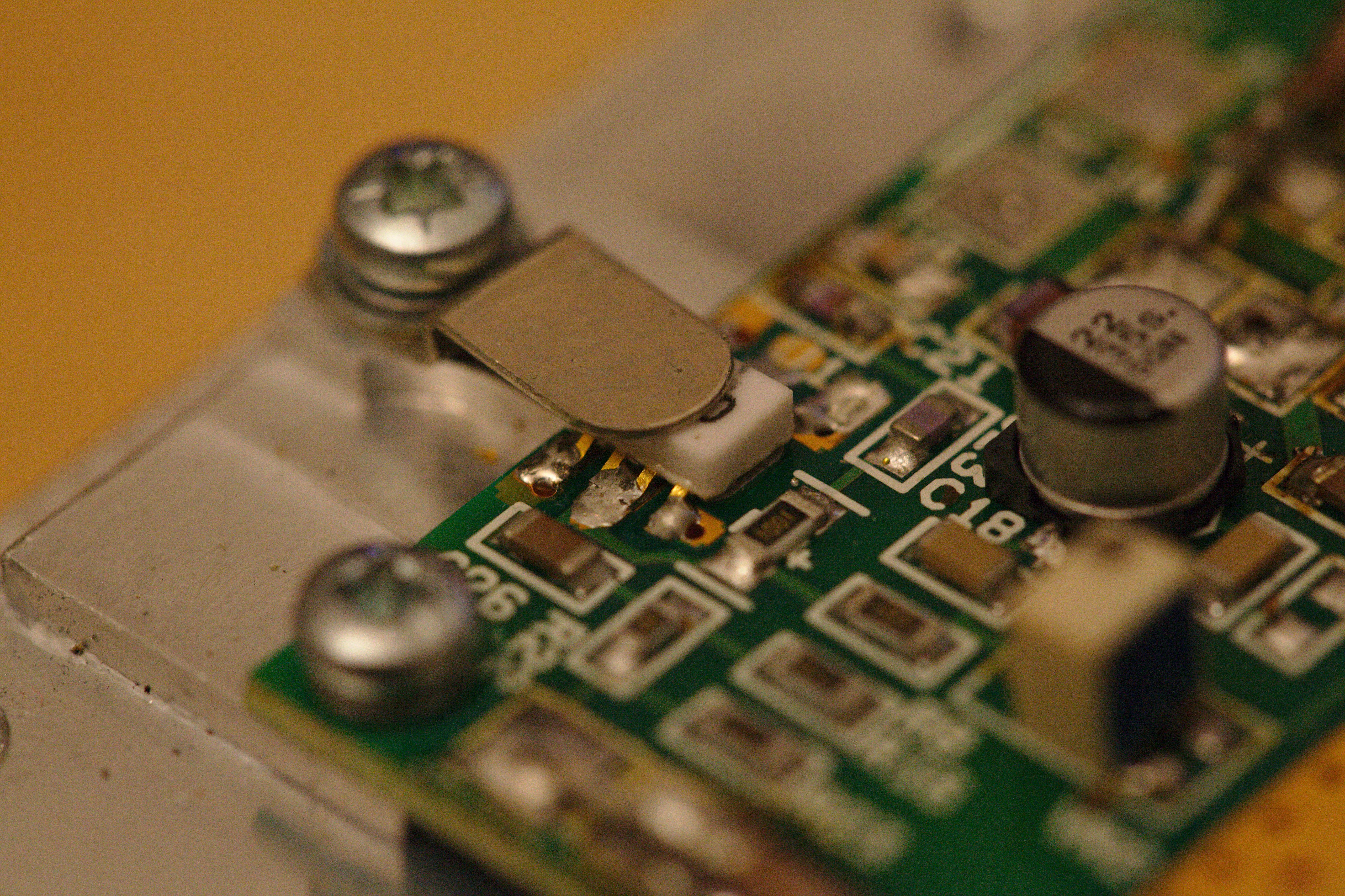
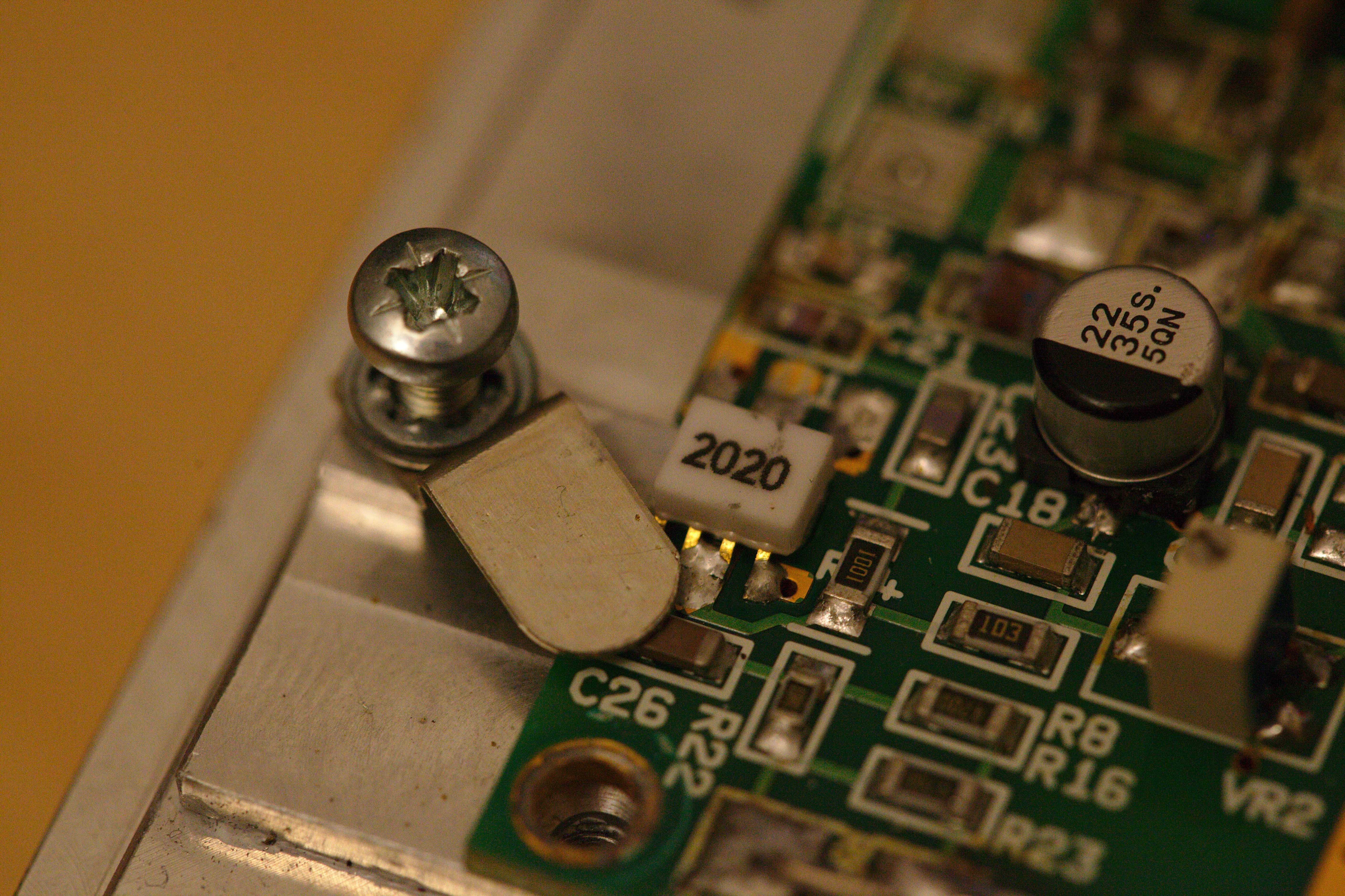
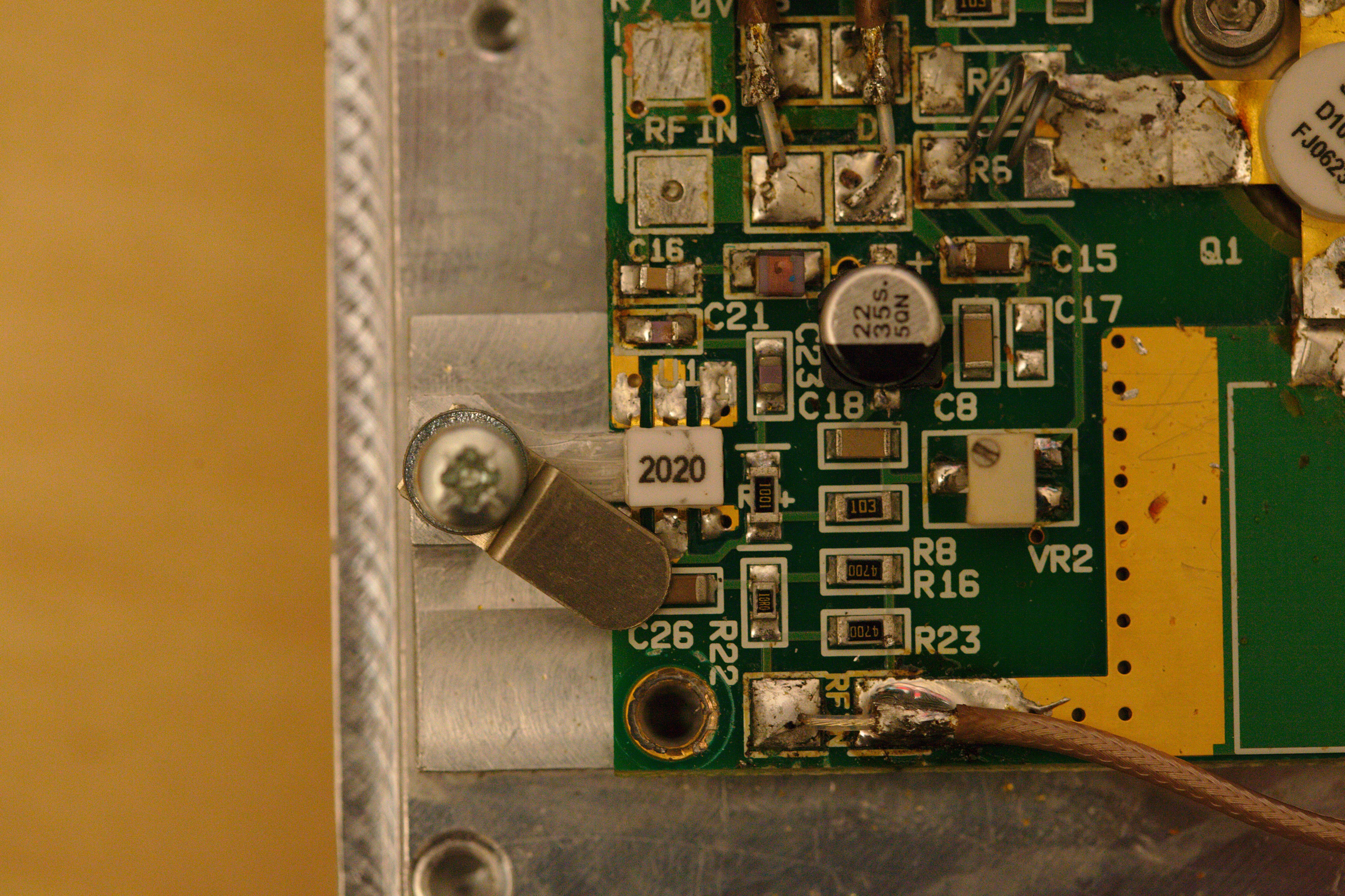
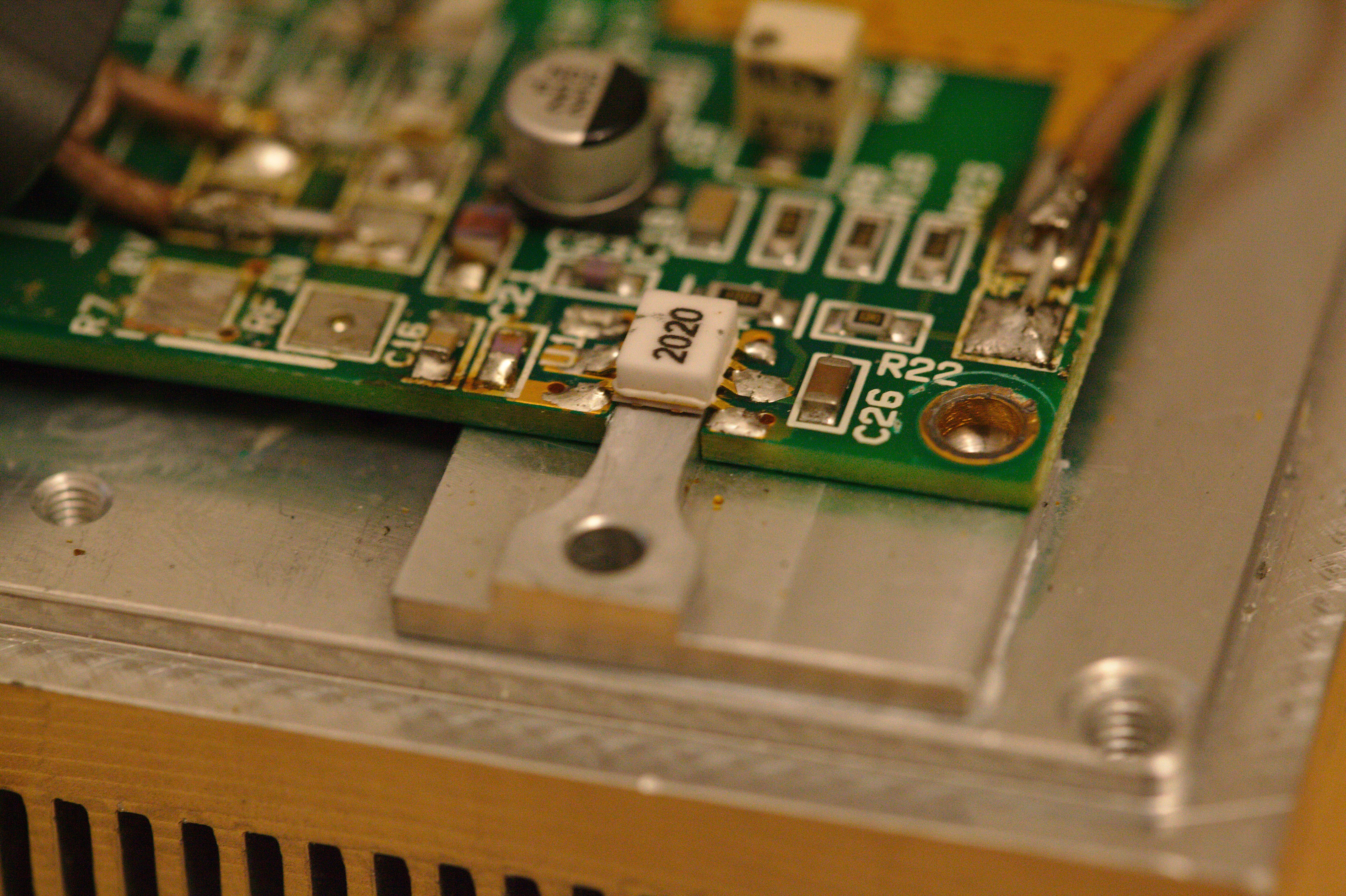
Unfortunately I could not find out what this "2020" part is. It looks like some pre-amp? Also that it's heatsunk from both top and bottom favours this theory. Inside the application note is a short block diagram, and I can identify the oscillator and mixer section to be on the I/O board, where the second board seems to be pure amplification. As the D1001UK is the output amplifier, this second "2020" chip seems to be the pre-amp.
But I'm certainly not that much of an electronic (nor RF) engineer, to know all the details ;)
The outside
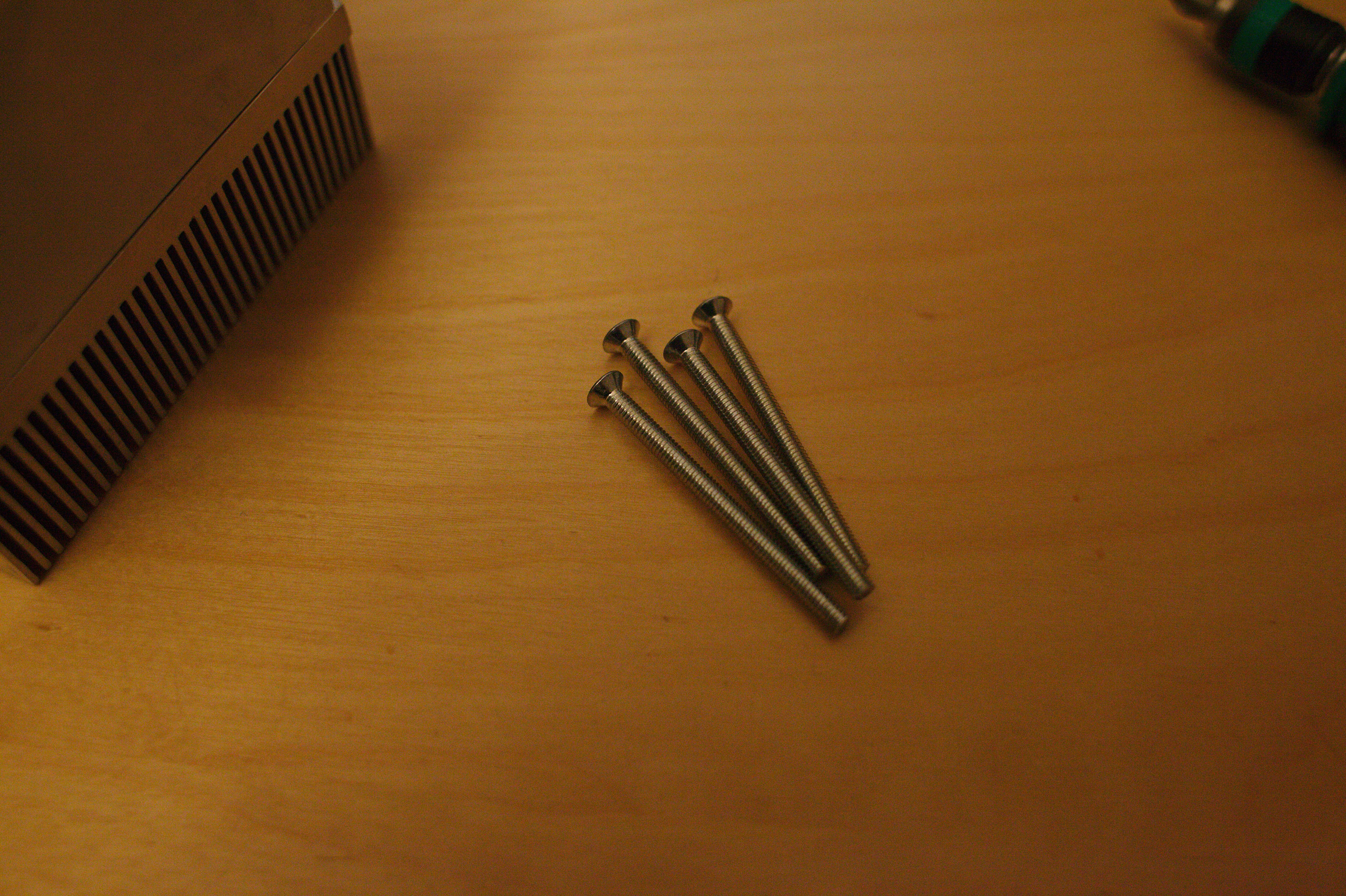
four screws hold togehter the case
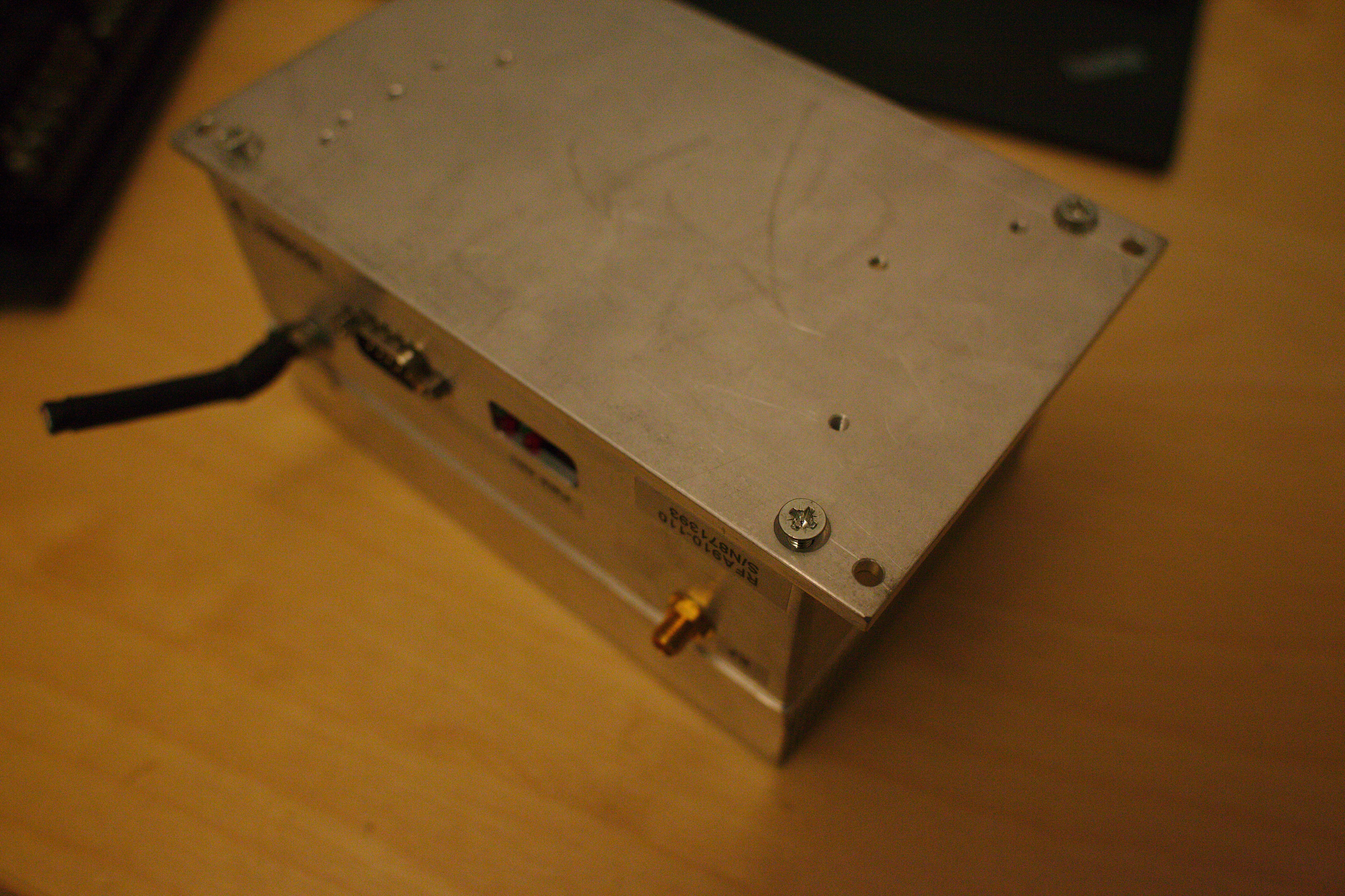
they reach down to the top
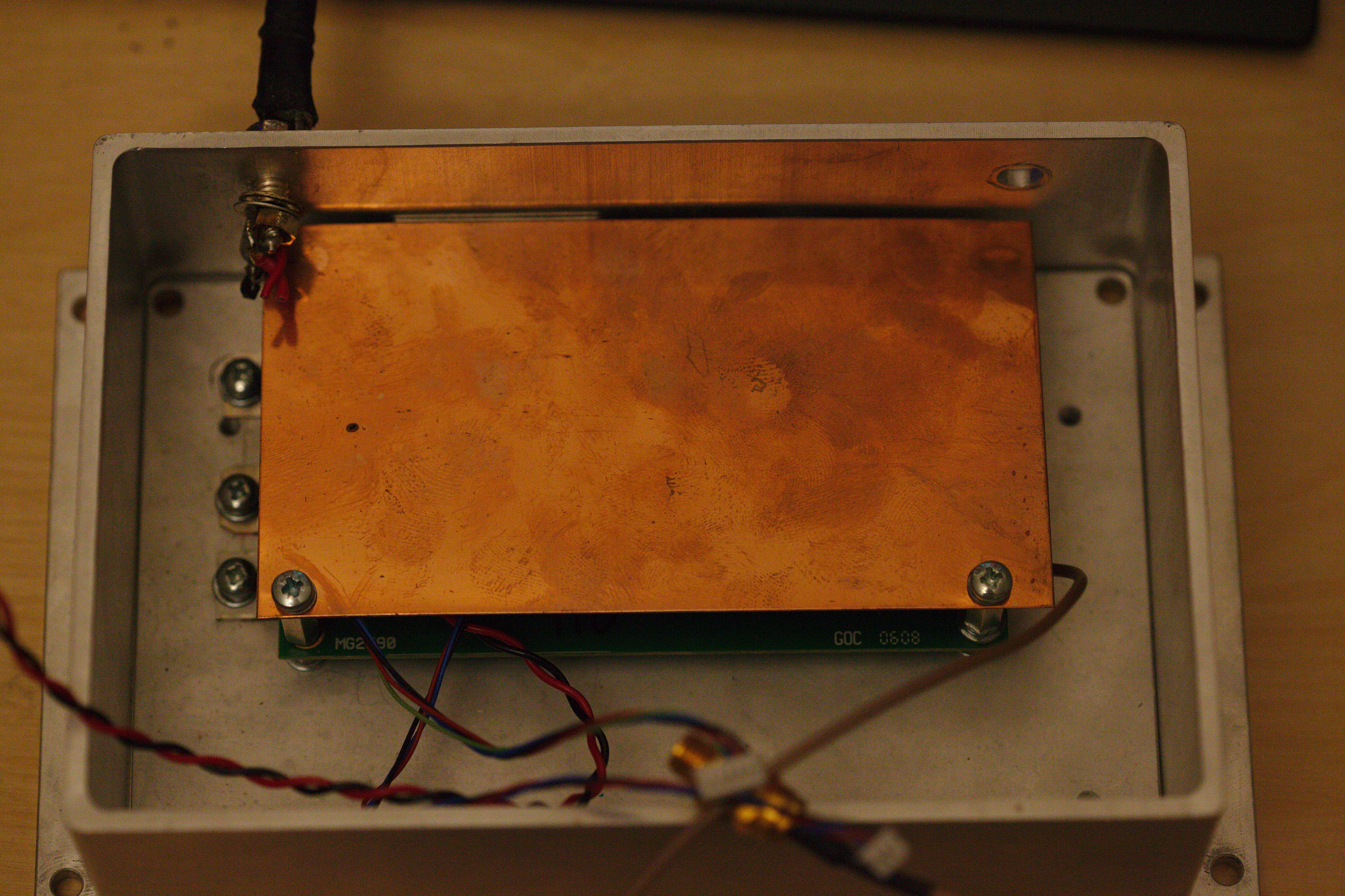
Inside. The construction is two boards, connected with the RF Line plus two data (?) connections
The power connections is very weird. It can not be loosened without cutting the wires. It seems it was not soldered for easy replacement...
The amplifier board
The output RF FET
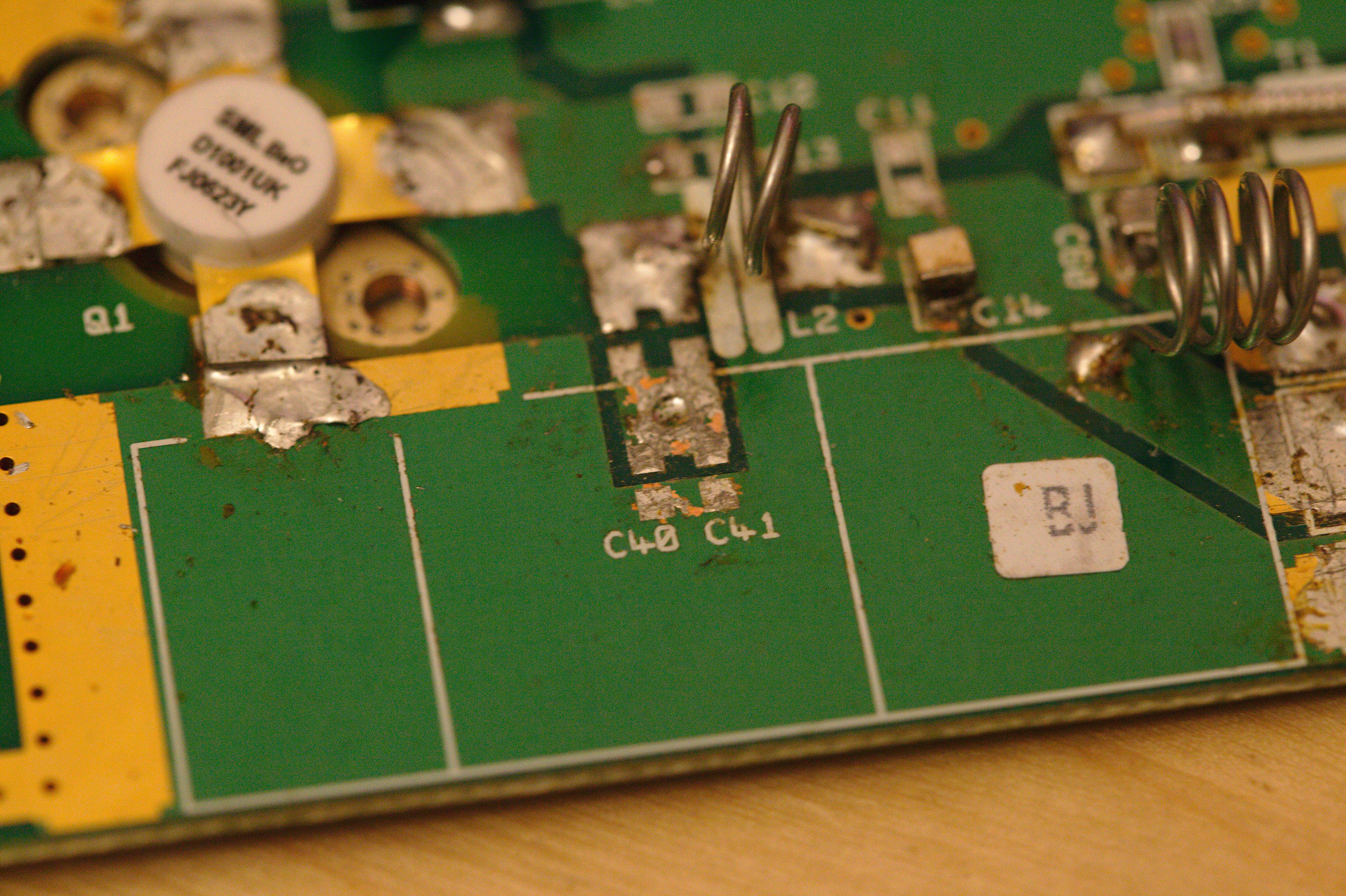
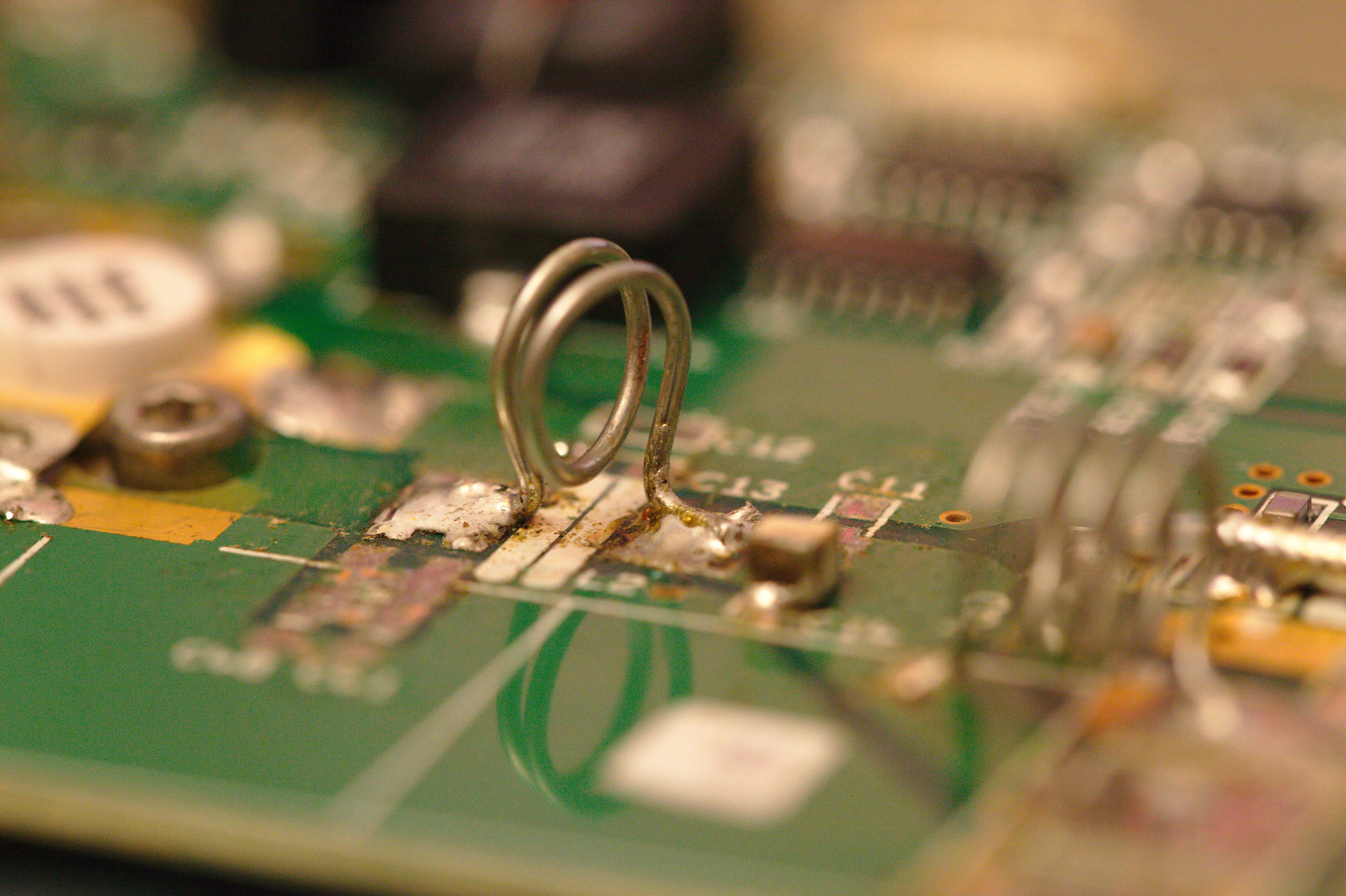
Hand bend inductors
Some chip with extra heatsink (Maybe the Preamp?)
Chips on the I/O board are screwed to the case
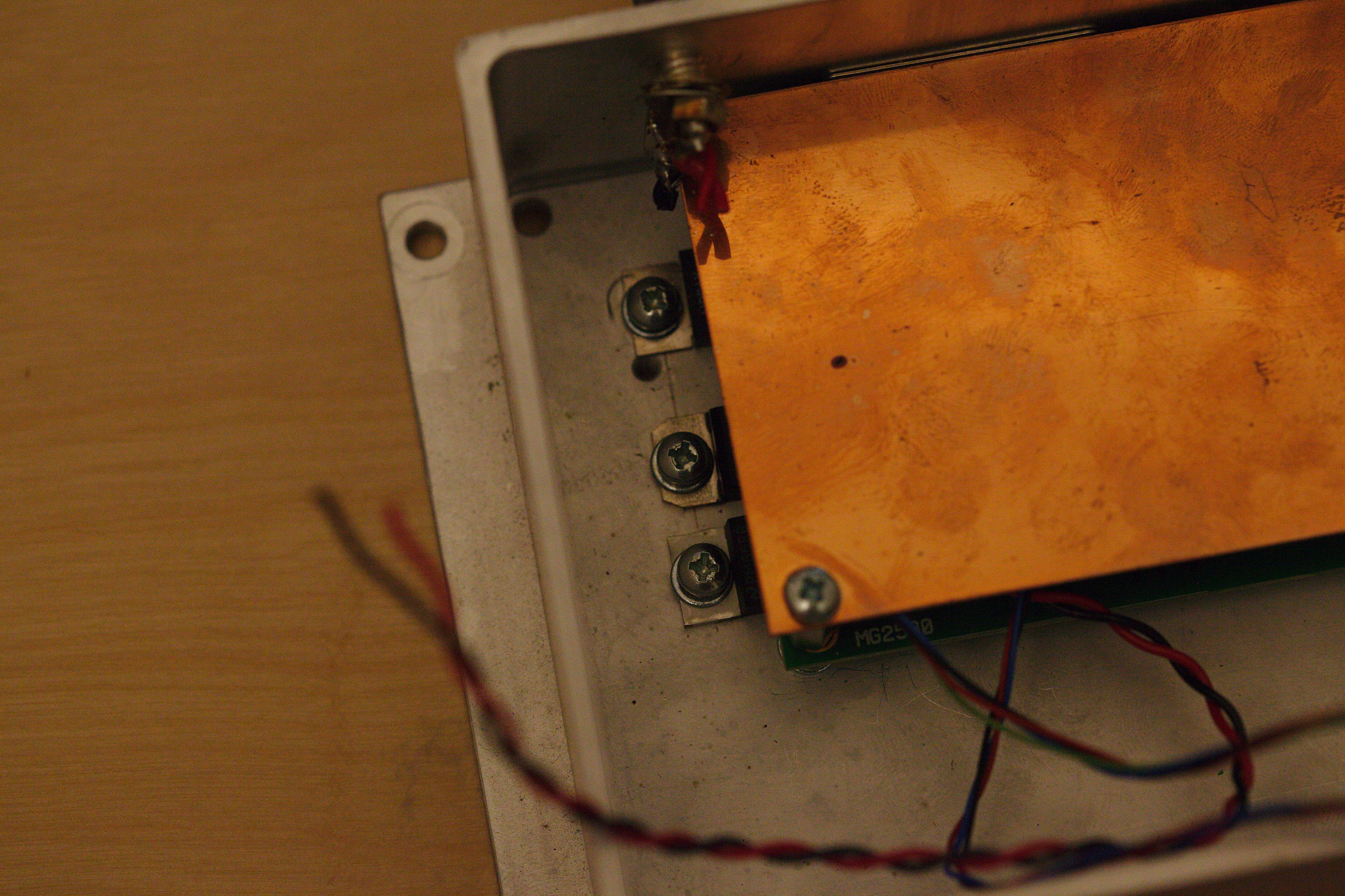
The I/O Board with copper shielding
The I/O Board, containing the oscillator (?)
On the amp. board: output capacitor

Same capacitor
Extra heatsinking for oscillator (?)
Some pot.
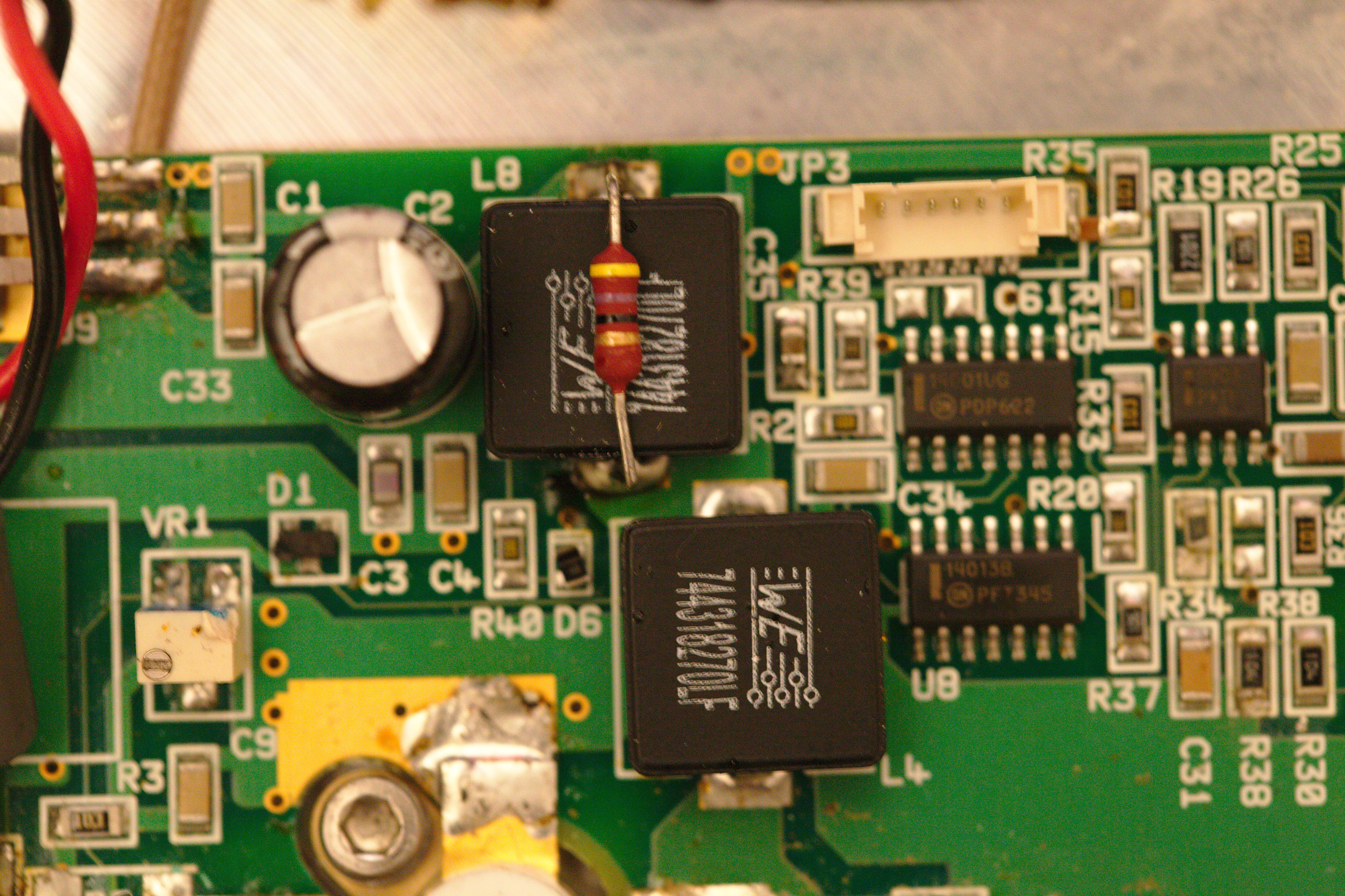
Würth Surface Mount Power Inductors
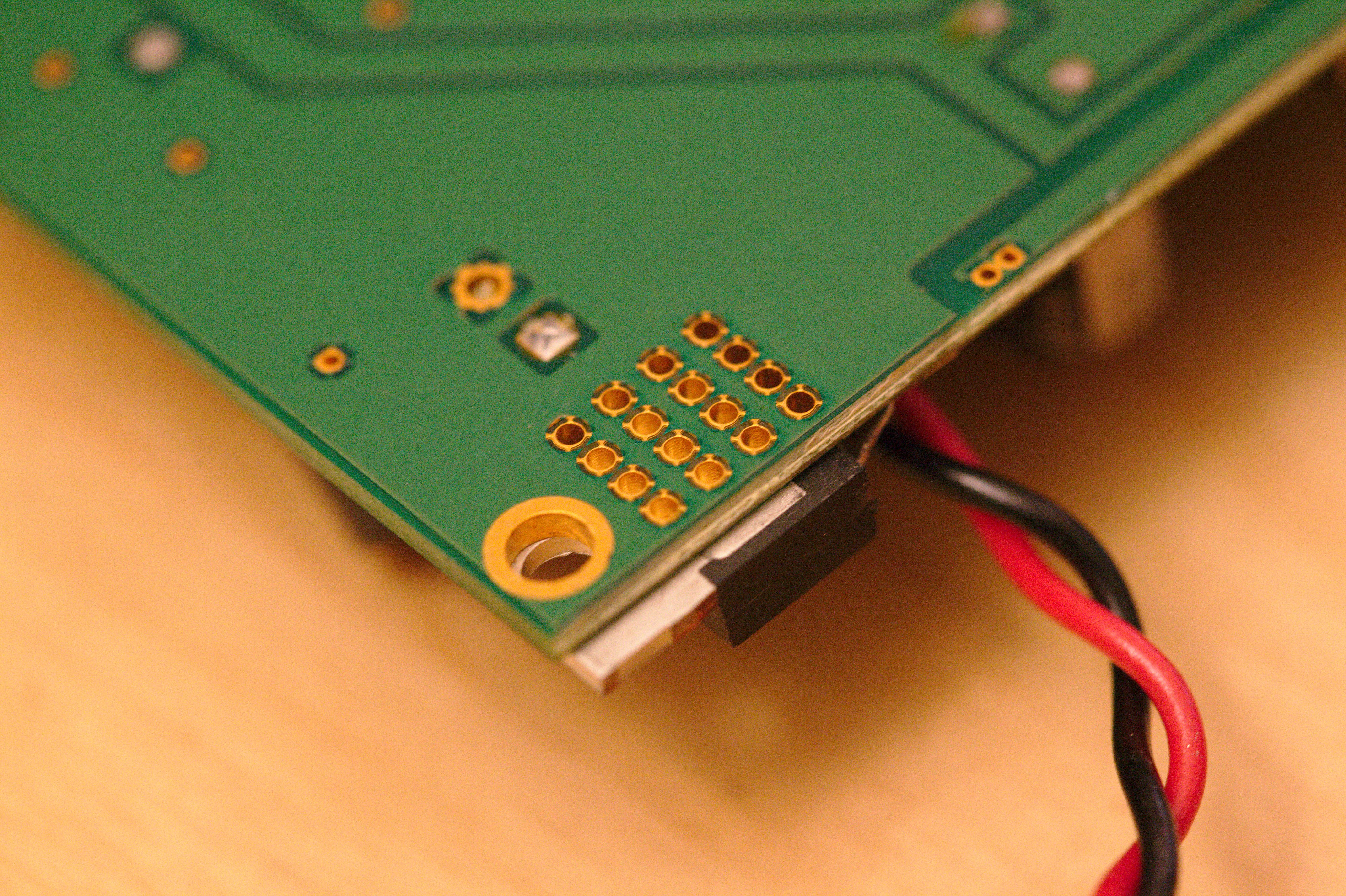
Bottom side of I/O Board
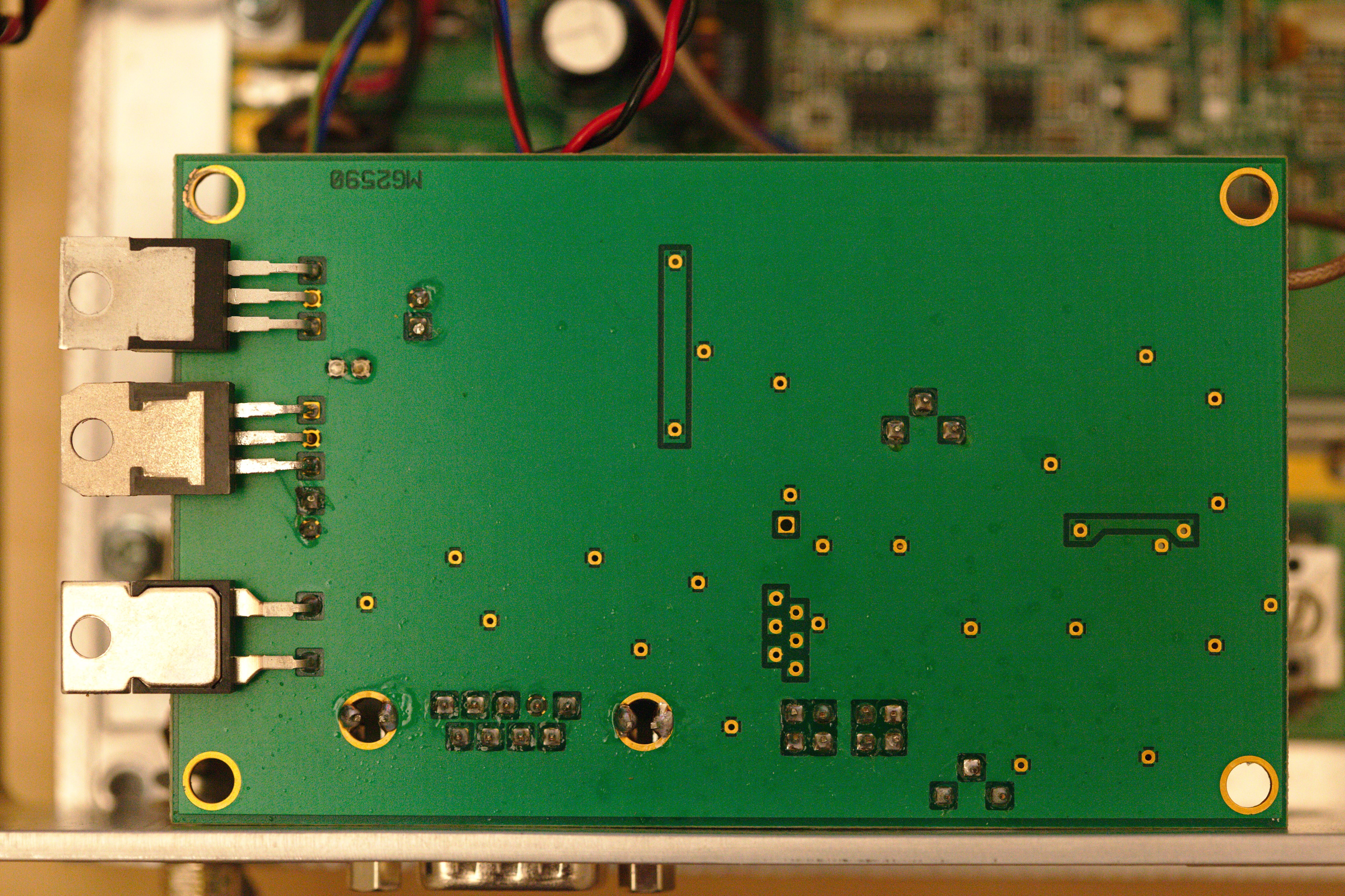
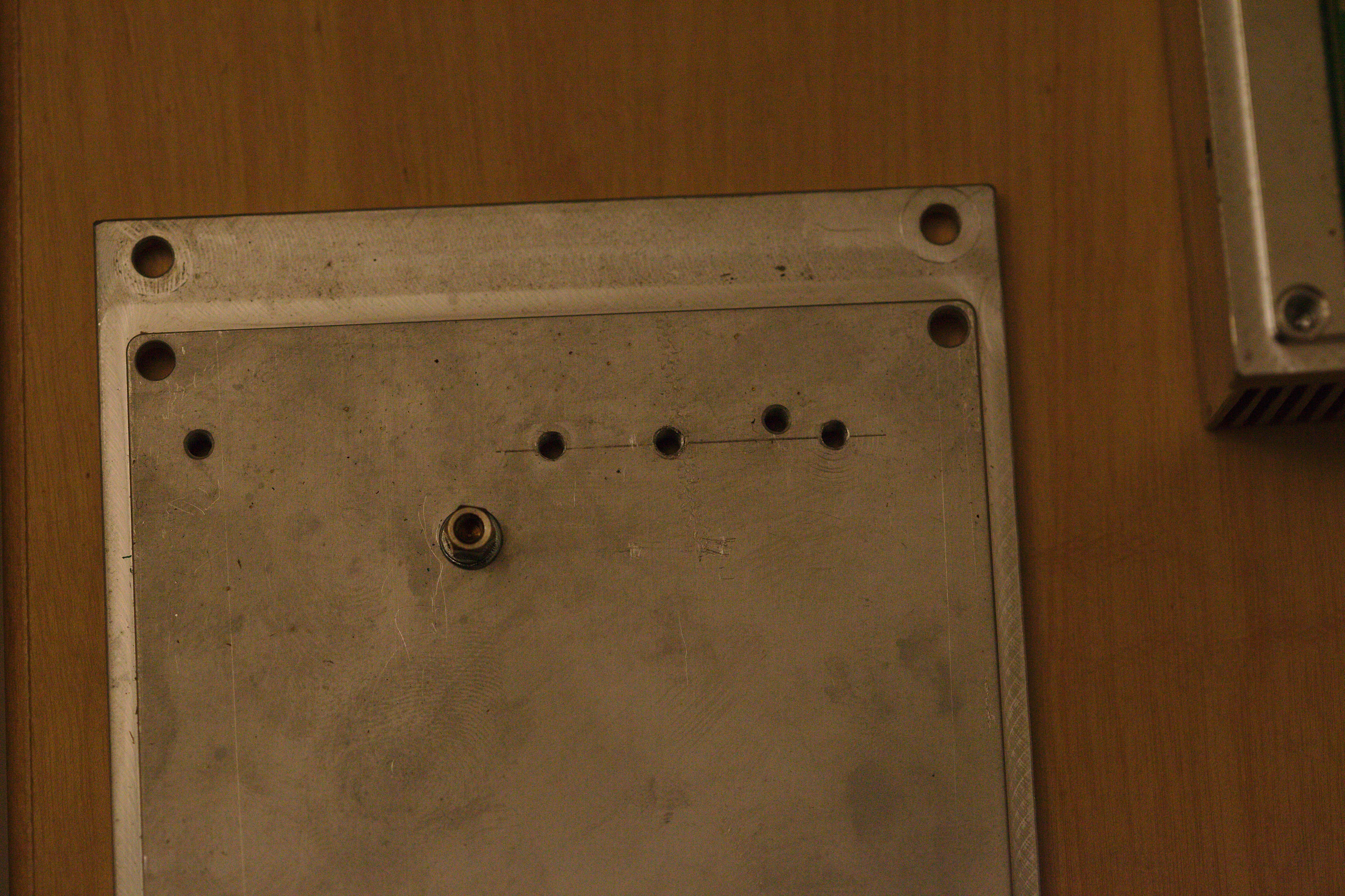
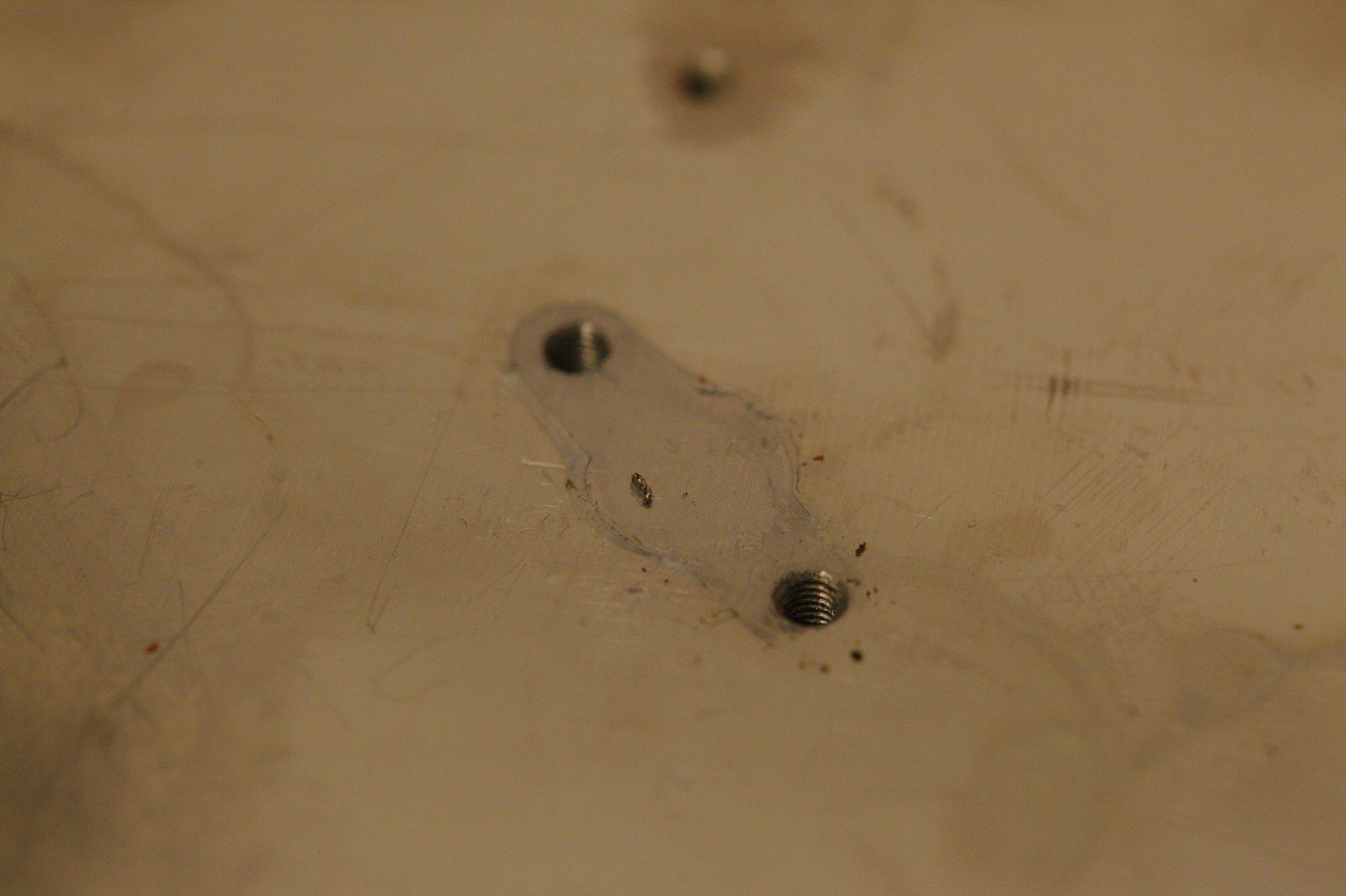
Marks from fabrication, looks like the casing was handdrilled
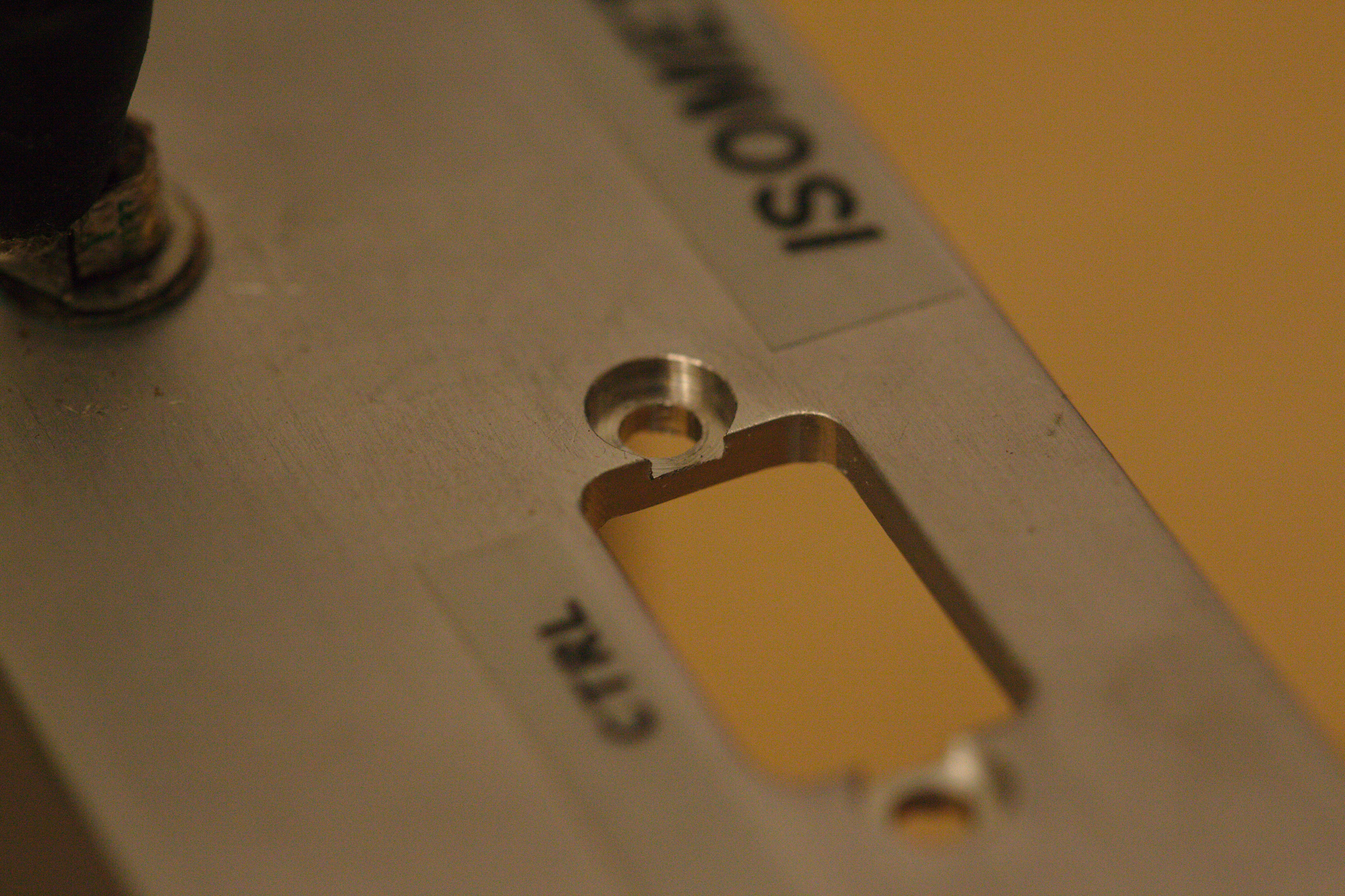
The did the effort to create a relieve for the screws of the DB9 connector
Beyond the heatsink
The whole Preamp (?) section
Nice details of the hestsink
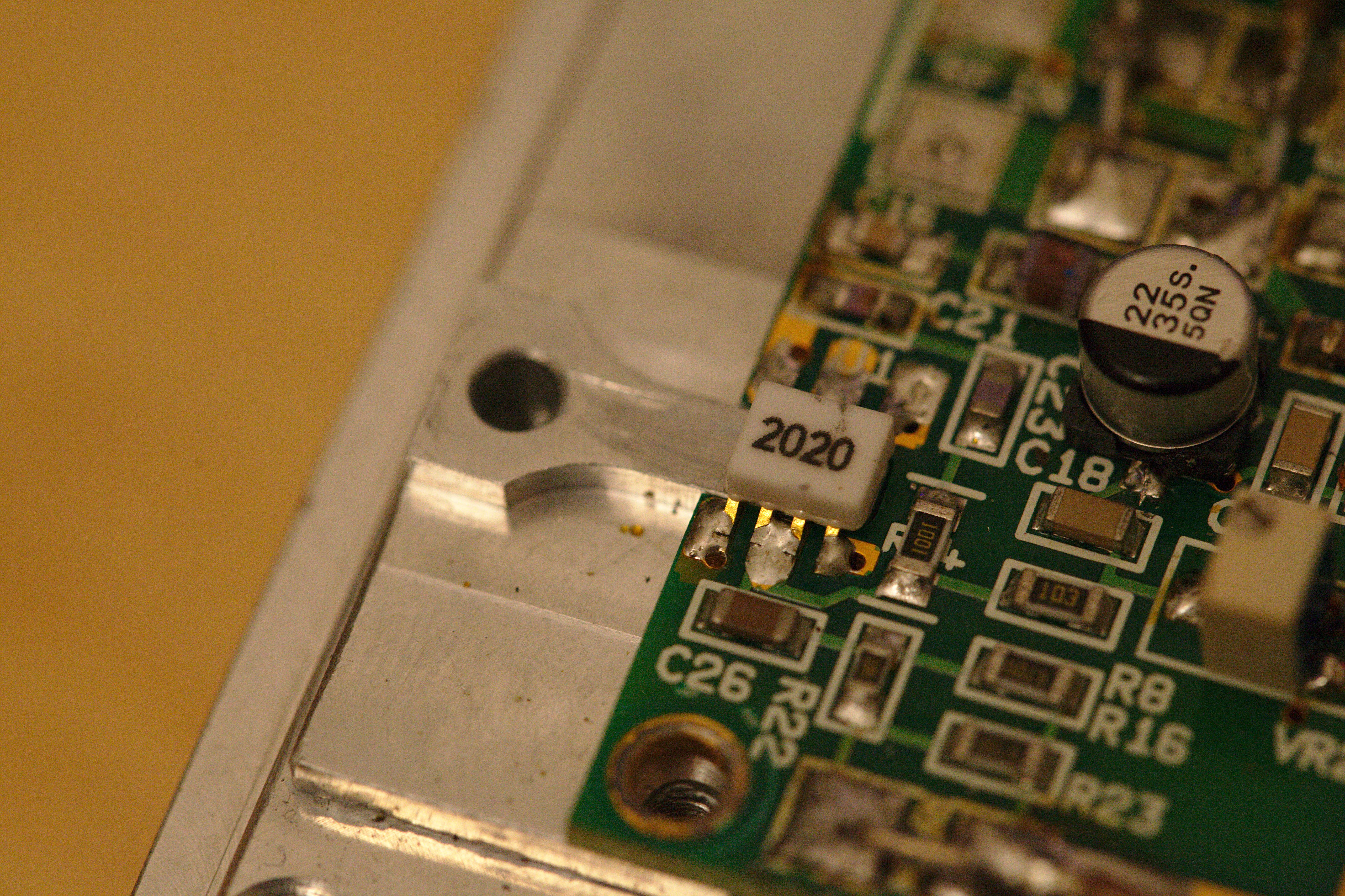
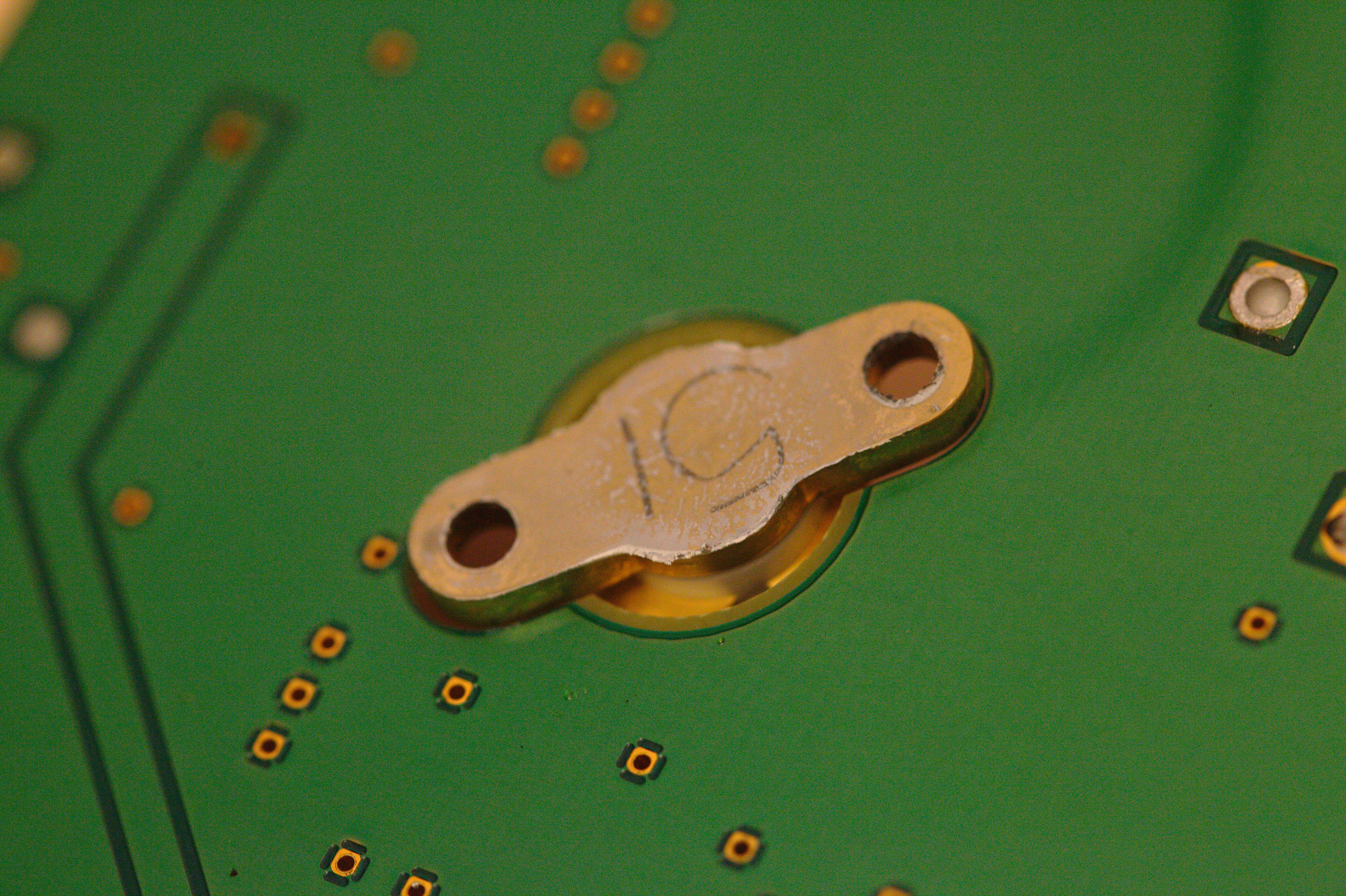
The PCB is cut out under the chip
Thermal paste under the RF FET does not look fresh
The RF FET from below
INTERLOCK connector
AIRPAX 6700 Series bimetal thermostat
Voltage Regulators on the I/O Board
Mhhh... Some transistor bodge?
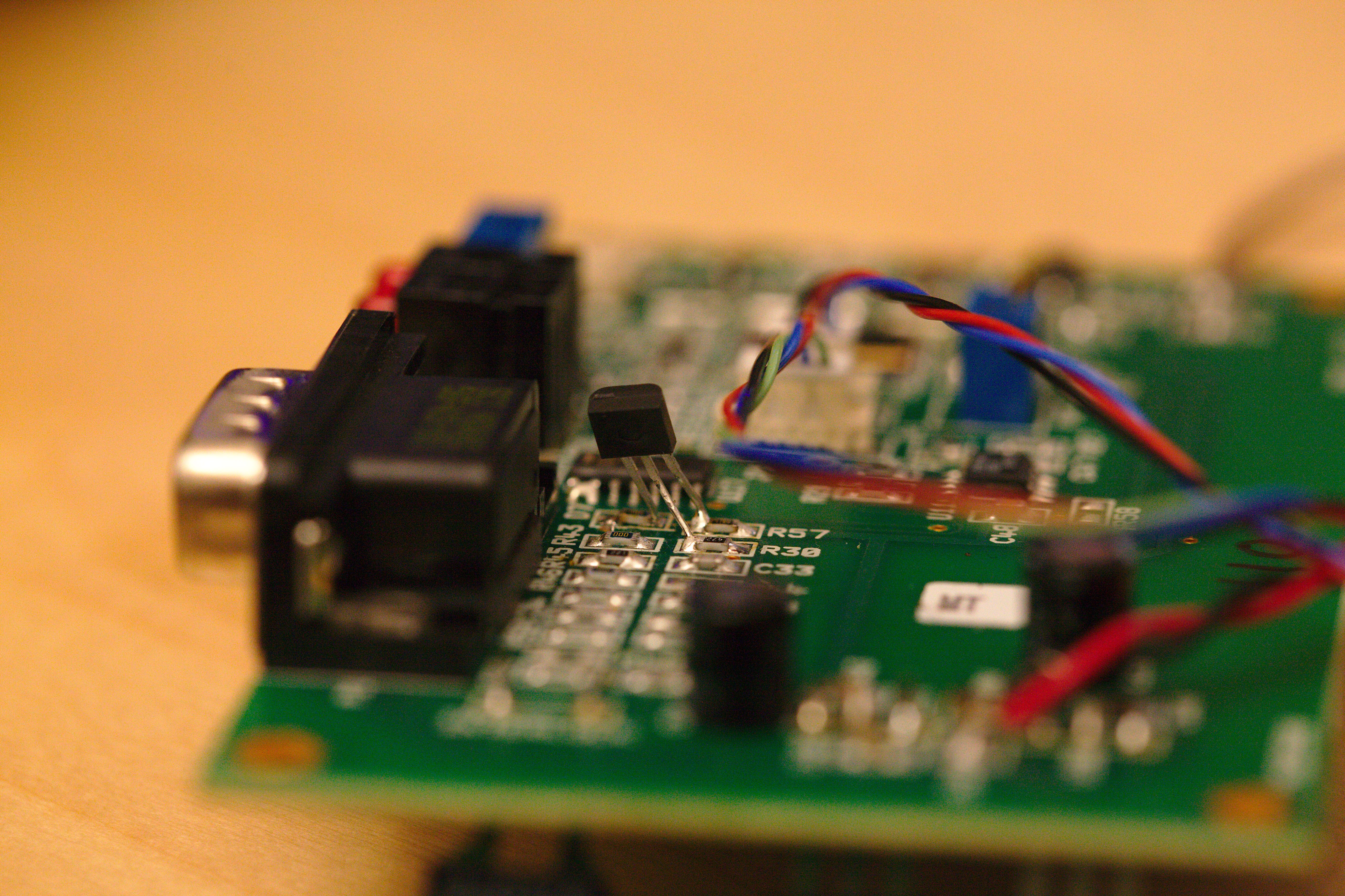
Another bodge
Thermal transfer beyond the LM340 on the amp board
Inductor, probably replaced sometime
Here are parts missing...